RF impedance matching using ferrite toroidal cores 4
Construction and testing
In previous articles we have discussed three commonly employed transformer families and some basic circuit formats used in impedance matching. This month we will consider assembly methods and performance testing, concluding with a farrago of circuits.
1 Core preparation
Before commencing construction, the first operation one should perform is the marking of the core body to facilitate later identification. There is bound to be some future use for these cores and unless they are identified now, the results of the next application will be uncertain.
Depending on which manufacturer's core is used and what part of the range it represents, there will be quite a variation of finish ranging from smooth, colour-coded enamelled surfaces to the basic uncoded, abrasive raw material.
In the case of the former finish, no surface preparation is required. With the latter however, it is essential to wrap the core with a protective covering in order to avoid damage to the enamelled winding wire during assembly. Virtually any non-conductive material may be used for this purpose. The cheapest by far is PVC tape. A word of warning however, especially if the assembly is to be used outside. Unless the transformer is mounted in a water/dust proof container (IP56) or the entire assembly is potted, the adhesive backing of the PVC tape will soon deteriorate and expose the enamelled wire and core to the elements with consequent deterioration and failure being inevitable.
A more durable and generally useful tape is EPR (ethylene/propylene/rubber) which has a high voltage rating in excess of 1000 volts, a temperature rating of 130 degrees Celsius (PVC is generally rated at 75 degrees Celsius) and, most importantly, has a self-fusing characteristic which eliminates the need for an adhesive backing.
To use, the tape is simply stretched and wound about the item to be covered. The individual layers after a few minutes combine to form a single piece seal.
Yet another method of protection is to paint or varnish the core. If it is painted, don't forget to identify the core after the paint has dried.
With low powered units, insulated hook-up wire or sections of ribbon cable may be used as the windings and can be applied directly to the untreated core.
2 Winding
Prior to commencement of winding it must be ascertained the length of wire required. One method is to wind a piece of string, the required number of turns, about the core. Add 10 percent more, plus the length of tails (ends). This saves wasting wire and the dissatisfaction of having to rewind because of insufficient wire to complete the necessary number of turns.
Windings may be laid flat about the core with the wires running parallel with respect to each other, or they may be twisted together prior to assembly and applied to the core as a single winding. See Figures 1 and 2.
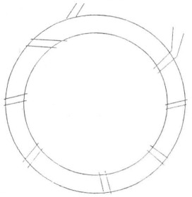
Fig. 1.
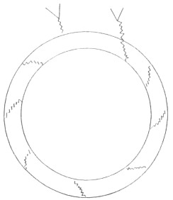
Fig. 2.
Whatever method is used, the windings should be spaced evenly over at least five-eighths of the core body. If, in the case of multiple circuits occupying a single core, each circuit should share an equal proportion of the core body. See Figure 3.
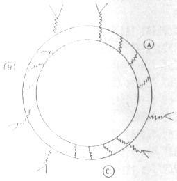
Fig. 3.
3 Twisted multifilar (stranded) windings
These are often more easily applied and, in case of transmission line and auto-transformers, provide for a more efficient power transfer than the flat parallel formation. Identification of windings is initially more difficult with this method but may be overcome by testing with a multimeter and then marking to suit individual requirements.
4 Circuit notation
The three types of transformers discussed are all drawn according to commonly accepted protocol. One difference however is the placement of a dot beside the windings to indicate the phasing or commencement of the winding. See Figure 4.
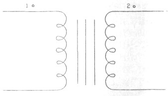
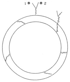
Fig. 4.
Take into account that which has preceded and apply the wire to the core. See Figure 5.
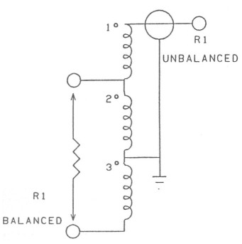
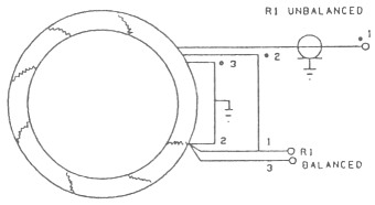
Fig. 5.
Transformer details
TYPE - 1:1 balanced to unbalanced auto-transformer.
WINDING - 1 trifilar winding tapped at the junction of the first and second windings and at the junction of the second and third windings.
CORE - FC564*, 43 Mix Amidon - FT140.
WIRE - Enamelled #20 - Metric equivalent 1 millimetre.
TURNS - 8 turns.
POWER - 100 watts PEP. This power rating coincides with the majority of transceivers currently in use in Australia and New Zealand.
FREQUENCY - 1 to 30 MHz.
* Core coding of Stewart Electronics. Cost of core approximately $6,18 each plus tax.
This balun would make an ideal addition to a G5RV antenna providing correct balance of current between the coaxial cable (unbalanced) feed and the 300 ohm ribbon (balanced) stub and would, without doubt, improve the radiation pattern of the antenna by correcting the current phasing of each leg of the dipole flat top.
NOTE: Although the nominal impedance of television ribbon is 300 ohms, because of the operation of the cable as a quarter wave stub in the G5RV, the reflected impedance at the junction of the ribbon and the coaxial feeder is about 75 ohms when the antenna is operated on its centre design band of 20 metres. This impedance alters from band to band, the difference showing as a VSWR of greater or lesser degree depending on the adjustments made by the flat top.
6 Testing
After constructing a transformer one may wish to test it for bandwidth and circuit integrity. Did we put it together correctly?
The least complicated test is to inject wideband RF noise into the transformer input. The output of the transformer is terminated in a resistance of similar value to the impedance of the load which will be placed on it in operation. A check of voltage transfer with respect to impedance transformation stability over the required frequency range is achieved by using a noise bridge in conjunction with a receiver to cover the frequency range under test. See Figures 6 and 7.
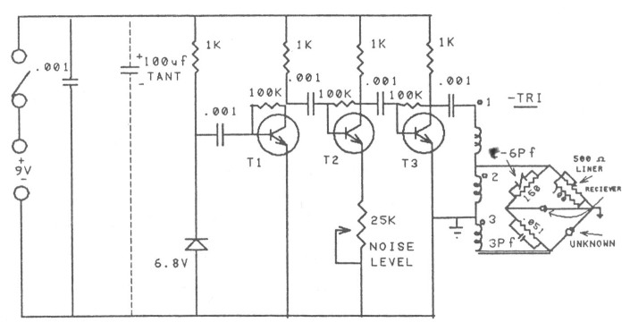
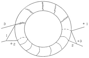
Fig. 6.
| T1, 2, 3 | BF198 or similar. |
| TR1 | 1:1 balun wound on FC470*, 77 Mix Amidon - FT50, using a bifilar winding consisting of windings one and two and a single winding for three. Enamelled wire, SWR # 20 or metric 1 mm using six turns per winding will allow operation over the range 1 to 30 MHz. The transformer should be wound according to the following ... Both windings must be wound in the same direction. The bifilar winding occupies the opposite half of the core body to the single winding. |
| R1 | 500 ohm linear taper carbon or plastic film potentiometer. |
| C | 100 µF tantalum required if external power supply is used. |
*FC470 Stewart Electronics stock number.
7 Testing method
Assuming that the noise bridge is operating correctly and has been calibrated...
- Connect the bridge and transformer according to Figure 6. R should be selected according to the load impedance to be used in the actual circuit; eg a dipole antenna equals 75 ohms.
- Set the noise bridge noise-level control to maximum and adjust the balance (resistance) to the known resistance (R).
- Set the receiver AGC to fast or disable it.
- Set the receiver to the lowest frequency of interest.
- Null the bridge as indicated on the receiver S-meter or by the receiver noise level. The position of the balance control when the null is greatest should coincide with the value of the load resistor (R) - given that we are testing a 1:1 transformation ratio. If the balance reading is not close to R, you have wrongly assembled the transformer, the core or the number of turns are not suitable for your lowest frequency.
- Carry out the same test as step e), at mid-frequency and top-frequency and note the position of the balance control at null. If your load resistance value R coincides with the noise bridge balance control at null for bottom, mid and top frequencies, you are ready for the next step which is to put the transformer into service.
Part 1 - Part 2 - Part 3 - Part 4
VK3HK, Stephen Bushell