Home - Techniek - Electronica - Radiotechniek - Radio amateur bladen - Ham radio - IMD and splatter
Interference has always been one of the greatest impediments to communications, regardless of frequency. If an amateur with a strong signal transmits right on a frequency where a weak signal is present, there is virtually no way you can copy the weaker signal unless the stronger station stops transmitting.
But, interference isn't confined to the simple case described above. Often there are other circumstances like IMD (intermodulation distortion) - often referred to as splatter on SSB. The latter may be transmitted, or locally generated in the receiver.
This month I'll review the subject of IMD /splatter, answer some of the most often asked questions, and discuss some recommendations and test methods.
CW transmission
Using CW provides a partial solution to the interference problem. Even if two signals are on exactly the same frequency, you can achieve partial copy of the weak signal when the strong signal is "key up." Also, if a weak signal is on a slightly different frequency from a strong one (perhaps as little as 1.0 kHz away), and the strong signal is not blocking your receiver, you may be able to separate the signals if you have a good narrow-band i-f filter (typically 500-Hz bandwidth) in your receiver.
There is a very basic reason why CW signals can be so easily separated. A good clean CW signal occupies very little bandwidth - less than 500 Hz, as shown in fig. 1A. This is only true if the oscillator in the transmitter is very stable and doesn't have any "phase noise."
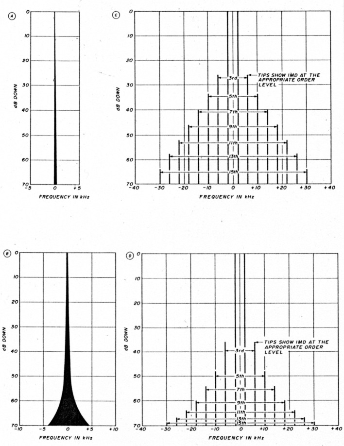
Fig. 1
(A) The output spectrum of a pure CW signal.
(B) The output spectrum of a typical CW signal with phase noise.
(C) The output spectrum of a clean SSB signal from a commercial amplifier.
(D) A typical Amateur SSB transmitter.
Phase noise is a form of frequency modulation that is often superimposed on the carrier frequency. As a result, a transmitted signal is broadened or spread out in frequency (see fig. 1B). This phenomenon is particularly evident in the modern-day synthesized transceivers. I often refer to phase noise as the "aurora" affect. If you tune a few kilohertz off the carrier of a CW signal with phase noise, it sounds like keyed white noise which is similar to the signal returning from the auroral reflection.
Further complicating this phenomenon is that the local oscillator in your receiver may also have phase noise, exacerbating the problem. It will be difficult, if not impossible, to determine whether the transmitter or the receiver, or both, are the culprits! For those who want more information on this communications bugaboo, I'd recommend reading reference 1.
SSB transmission
As if the problems of CW transmission weren't bad enough, enter an SSB transmitter and you have a whole new ballgame. By nature an SSB signal has a broad bandwidth, typically 23 kHz at the half-power point, when carrying voice intelligence.
In the good old days, SSB signals were generated by the phasing method because it was low cost and had good fidelity. Phasing exciters characteristically have wider bandwidth because the filtering and phasing required is more complex.
Most modern exciters generate SSB by the rf-filtering method which employs well-controlled crystal band-pass filters. However, even these filters are seldom specified over more than a 40-dB range.
The local VHF/UHFers can tell when I alternate between my phasing and filter SSB exciters. The phasing exciter has good audio fidelity, but the IMD outside the passband is at a higher level. The filter exciter has poorer audio fidelity, but outside the passband IMD drops off at a faster rate.
What most Amateurs tend to forget is that SSB signals, by their very nature, have "controlled" IMD. Amateur SSB exciters and power amplifiers are often specified to have a typical IMD specification - 26-30 dB at a specific PEP output level. This means that the third order IMD products (the ones generated closest to the desired signal but outside the 2.5-3 kHz passband), are only 26-30 dB below the peak power level specified. Higher order sidebands are also present, but usually at a lower level.
Figure 1C puts all this in perspective. It shows the typical output spectrum from a "commercial quality" . filter-type SSB transmitter when modulated by two identical level audio tones, one near 500 and the other near 2500 Hz (adapted from reference 2). Remember that this spectrum display is typcially 6-10 dB better than the average Amateur transmitter.
Referring to fig. 1C, note the high level of rf at the 3rd order level - typically 36-dB down. Consequently, there will be rf energy outside the normal 23 kHz passband that will be only 36-dB below the carrier peaks, or about one four-thousandth of the peak power. Not bad if the station is only 25-30 dB out of the noise, but very objectionable if it's 40-60 dB out of the noise.
What about the higher order side-bands? The 5th, 7th, and 9th order IMD products are still only down 4860 dB. They will be very noticeable on a strong local station which is typically 60-80 dB out of the noise!
To the average HFer, these problems may be an annoyance. With heavy interference, local noise, and intermittent operation (like a "DX pileup") you can learn to "live with it." However, to the VHF/UHFer who often listens on a relatively quiet band over a limited frequency range, IMD can be difficult to tolerate.
SSB splatter
So far I've been talking about the idealized transmitter case. What's it like when the IMD levels of an SSB transmitter are at Amateur specifications? Worse yet, what happens when an Amateur is trying to "eek out" the last bit of transmitted power by shouting into the microphone or turning the gain control up too high?
Figure 1D shows one possible spectrum display. This is a typical Amateur transmitter output spectrum at rated power output. Note that the 3rd order IMD products are only 26-dB below the peak power level. Furthermore, the 9th order products are 46-dB down, 14-dB worse than the commercial transmitter! Remember that if the transmitter is driven above these levels, the IMD will increase dramatically.
Why is this true? The linearity of a transmitter is limited by the ability of each stage to accurately reproduce and amplify the input signal. Each stage, usually a vacuum tube or solid state device, has a finite output power level beyond which it will generate distortion. Exceeding this level results in high levels of IMD and splatter.
Transmitting devices
Let's compare some typical transmitting devices. Vacuum tubes have been around a long time and maintain a good reputation when used as rf power amplifiers. RF transistors are in wide use, although they are often unfairly targeted as "splatter generators." More on this shortly.
Operating each stage of a transmitter in class "A" would be ideal for linear operation, but the power consumption would increase. The power dissipation of each stage would also be high, making the cost of the appropriate high power amplifier devices prohibitive. On the other hand, operating each transmitting stage in class "C" would raise efficiency, but distortion would be prohibitive.
As a result, most vacuum tube amplifiers are operated in class "AB" with moderate idling current. Vacuum tubes are usually large and, if they can't dissipate heat easily by themselves, heat dissipation can be assisted by a fan or blower.
Cooling solid-state devices with their very small geometry is still a problem, but one that is improving. Large heat sinks and special compounds are used to thermally bond the devices to the heat sink. Also most solid-state devices are operated in class "B." However, they are more prone to distortion.
Another reason vacuum tubes are so linear is that they operate with high voltages on the anode. Consequently, there is a large voltage difference between the typical operating voltage on the anode and the minimum voltage across the anode when saturation occurs. If you go back to old vacuum tube literature you'll find lots of discussion about "load lines." In the typical vacuum tube application the load line operates over a very wide voltage swing before saturation and distortion occurs. Furthermore, vacuum tubes usually operate with output impedance levels of 1-5,000 ohms. This is a moderately easy impedance to match to 50 ohms; it's often done with a pi-network. As a result, impedance matching losses are usually low and efficiency is high.
Contrast this with the typical solid-state power amplifier used by Amateurs. It most often uses transistors specified for 12-14 volt operation because this is the voltage usually used in mobile operation, and therefore in Amateur shacks. These devices typically saturate at 1-2 volts, so the load line operates over a very narrow voltage range.
The operating impedance levels of the typical rf solid-state transistor are low, usually 1-10 ohms! This makes the matching networks more complex and lossy. At UHF frequencies the parasitics of the components themselves become a major problem.
The use of higher voltage transistors like the 28-volt types will improve linearity, but require higher supply voltages at lower current. The development of MOS (metal oxide semiconductors) power FETs is a promising field. These devices usually require a 25-60 volt supply, although some lower-power types operate at 12-14 supply voltages.
Proper amplifier operating parameters
Now let's look specifically at power amplifiers. It should be obvious why just about all Amateur amplifiers, especially the commercial types, operate in linear service. Linear amplifiers are less likely to abruptly change power and can be used on any emission type: CW, FM, SSB, or ATV.
Vacuum tubes are still the favorite source of linear power, especially when good IMD and power levels over 100-200 watts are desired. But, the fact that an amplifier uses a vacuum tube is no guarantee that it will be linear. Certain operating parameters must be met. Many of them are described in references 3 and 4. Furthermore, what is often ignored is that for good IMD performance, the type of tube selected is often more important than the operating parameters. If the tube you choose isn't specifically designed for linear service, you probably won't obtain good linear output characteristics - regardless of the operating parameters and circuitry employed.
Generally speaking, at VHF/UHF frequencies, tetrodes have the highest power gain and are usually operated in the grounded-cathode configuration. However, the newer high-mu triodes driven in the ground-grid configuration, while having less gain, will generally deliver the best IMD performance.
Table 1 shows the expected linear performance from some of the most popular tubes Amateurs use. Data has been gleaned from manufacturers data sheets and literature.(5)(6)
Information on older tubes (prior to 1970) is almost nonexistent. From the table, it is obvious that the newer bigh-Mu triodes generally have better IMD performance. Additional parameter information is available in reference 3.
One further caution. The IMD shown in table 1 is an optimized target figure and will vary somewhat with different tubes. These numbers were probably derived under tight laboratory conditions with good instrumentation.
Table 1 is by no means complete. Always get the exact parameters directly from the manufacturers data sheets, not "Joe Ham" down the street. Deviating from the specific operating voltages shown on these data sheets will probably degrade the IMD.
| Tube type | Dissipation in watts | Peak envelope power output | IMD specs | Remarks |
|---|---|---|---|---|
| Triodes | ||||
| 3CX400A7/8874 | 400 | 590 | 35 | |
| 3-400Z/8163 | 400 | 590 | 28 | |
| 3CX800A7 | 800 | 750 | 36 | |
| 3-1000Z/8164 | 1000 | 1080 | 29 | |
| 3CX1500A7/8877 | 1500 | 2000 | 38 | |
| 8938 | 1500 | 2000 | 44 | |
| Tetrodes | ||||
| 4CX250R/7580W | 250 | 470 | 23 | |
| 8930 | 350 | 350 | 27 | Formerly DX393 |
| 7650 | 600 | 680 | 31 | |
| 4-1000/8166 | 1000 | 1540 | NA | IMD Estimate 25 dB |
| 4CX1000A/8168 | 1000 | 1400 | 23 | |
| 7213 | 1500 | 1000 | NA | IMD Estimate 25 dB |
| 4CX1500B/8660 | 1500 | 1500 | 43 | |
NA: Not available
If a tube is driven to higher power levels than shown, the IMD will drop accordingly. As a rough rule of thumb, every time the power output is doubled, the IMD will degrade by at least 6 dB. Going above the output power shown on table 1 is strongly discouraged, unless you want to severely shorten the life of your tubes. Furthermore, you'll gain the ire of every VHF/UHFer in your area who'll be telling you how badly you're splattering.
Solid-state power amplifiers are popular, especially those delivering 10-160 watts. They are generally small in size and only require a single power supply voltage. Reference 7 describes them in detail, along with recommended circuitry. As stated above, the 12-14 volt transistor types are the most common. Some precautions are advised. The power supply should be fairly well regulated and, preferably, adjustable.
Most solid-state amplifiers are specified to operate at approximately 13.5 volts. Dropping the power supply voltage to 12 volts will usually drop the output power by 10-20 percent! Likewise, the IMD will severely degrade.
Pay special attention when wiring the power supply to a solid-state power amplifier. Large diameter wire, no. 14 or larger AWG, is recommended since these amplifiers draw from 5-20A. Small diameter wire will cause a large voltage drop on the power supply lines, with a commensurate decrease in output power and IMD as described above.
As mentioned earlier, solid-state power amplifiers have developed a bad reputation with regards to splatter. There are many reasons for this. As I noted above, the power supply and supply voltage are sometimes to blame. But, the biggest offender is probably the user and his or her interpretation of the manufacturers' specification.
For example, a typical amplifier specification may say "100 watts output with 10- watts of drive." This implies that the amplifier has a true gain of 10 dB.
In reality, the 100 watts of output power may be the maximum output power possible from the amplifier, not the maximum linear output power. Also, the gain may be much higher at the lower output power. Lastly, you may be overdriving the amplifier.
Testing and evaluating power amplifiers
Up to now I've been describing operating parameters. Now let's dig in and see how to test, evaluate, and operate a linear power amplifier. Then you'll be able to better apply this information to your own station.
To better illustrate the point of linearity and specifications, I've plotted on fig. 2 the true output versus input power on a typical Amateur commercial 100-watt VHF solid-state power amplifier. Figure 2 shows that an input power of 1.0 watt yields an output power of approximately 23 watts - a gain of 23 or 13.6 dB. At 3.5 watts input, the output power is approximately 64 watts, a gain of 18.3 or 12.6 dB. Finally, at 10 watts input, the output power is approximately 100 watts; the gain is 10 dB.
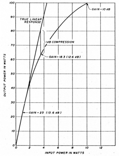
Fig. 2 - The graph shows the input versus output power from a typical VHF Amateur commercial amplifier. See text for further information on how to interpret the results and perform your own tests.
Note that the gain isn't constant. What went wrong? The answer is nothing. This output versus input characteristic is typical of the solid-state power amplifiers used by Amateurs. They are linear, but only up to a point.
In a true linear amplifier, a 1-dB input power increase would yield a 1-dB output power increase. In the case of solid-state power amplifiers, linear operation is generally acceptable up to the "1-dB compression point" - the output power level where the gain of the amplifier drops 1.0-dB below the low-power gain.
Said another way, the 1-dB compresssion point is the output power level where the amplifier output increases only 9 db for a 10 dB input power increase. Above this power level distortion and IMD increase rapidly.
Fine you say, but how do I test compression? The easiest way is to use two power meters, one at the input and one at the output of your amplifier (see fig. 3). Measure the output power at 5-10 different power levels. The greater the number of data points taken, the greater the accuracy. Plot the results as shown in fig. 2.
Next, draw the "true linear response line" from the origin as shown on fig. 2. The 1-dB compression point is the measured output power-level which is 80-percent (- 1 db) below the expected output power (64 versus 80 watts in fig. 2).
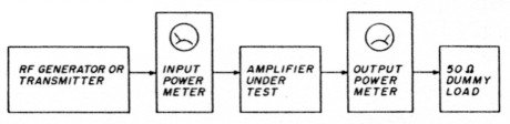
Fig. 3 - This diagram shows a recommended test set up to measure the linearity of a power amplifier as described in the text.
Power meters
There are several other things to remember when operating a linear. You must have a power meter; an external one is preferable. Without a calibrated power meter you'll never be able to determine if your equipment is operating properly.
There are several caveats when using a power meter. First, they all have a time constant. It takes time for the peak power to register, if in fact it ever does. This means that on SSB, the peak power you are running should never show on the meter. If it is, you're driving the rig too hard!
When using a typical power meter, you should be averaging about 25-30 percent of full linear power (1-dB compression point) capability. Never exceed 50 percent (see reference 7). Test your linearity, then advance the microphone gain on your exciter and observe the output power. If you ever reach a point where output power no longer increases with increasing microphone gain, back it down!
Say you have an amplifier that puts out 100 watts of linear power, after measuring it according to the methods described above. Set your gain control on the rig so that on average voice it is indicating 25-30 watts, as shown in fig. 4. This goes a long way towards insuring that you are not splattering excessively and will still be transmitting full power on peaks!
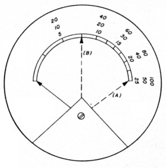
Fig. 4 - This diagram shows the face plate of a typical RF power meter. A is the key-down needle position for maximum linear power. B is the recommended needle position when operating SSB for same as described in text.
If your power amplifier has too much gain (the most typical case) you'll have to be careful to keep the microphone gain turned down, or place an attenuator between the exciter and amplifier, or both. You can use a piece of RG-58 cable as an inexpensive moderate-power attenuator.(8) At about 4-5 dB per 100 feet at 2-meters, you may only require 25-75 feet.
If you have ALC capability, use it! It's a great way to control the tendency to overdrive a rig, especially if the amplifier has too much gain.
Other tips
Never use an amplifier unless it's necessary. Remember the FCC regulation that Amateurs should use the minimum power required to maintain communications.
If you overdrive your rig, your signal may still sound great to the station listening to you! Try an A/B test. Switch your amplifier in and out, and have a local station observe the change in signal strength to verify that your gain increases by the number of dB expected from the power amplifier. Then have them tune off 5-10 kHz and repeat the A/B test to see if the IMD degrades with the power amplifier in line.
Remember that all IMD power is wasted and serves no purpose other than to cause interference to adjacent channels!5 Excessive power and overdrive, especially on solid state amps, can also cause premature death to the output devices.
Despite stories to the contrary, the gain of vacuum tube VHF/UHF amplifiers is finite, typically 10-17 dB. Don't expect a 10-watt exciter to drive a 1000-watt amplifier to full output power. You may still need a driver amplifier ahead of the final.
Test all new gear with a local. Problems such as misalignment and breakage can occur during shipment. Carrier supression is sometimes a problem, but can usually be retweaked. In rare cases, power amplifiers may have to be re-peaked.
RF actuated power amplifiers can often cause a problem at lower power levels because they may not turn on properly. If possible, try to hard wire the switching on these amplifiers to the station or exciter T/R line.
RF compression is another topic that is really beyond the scope of this month's column. Suffice it to say that if you have it, try it, but only when necessary on weak signal paths. Adjust it carefully and don't use any more compression than necessary! Remember that rf compression significantly increases dissipation in the power amplifier, which could destroy or shorten device life.
Finally, for many years VHF/UHFers have been gathering at conferences to shoot the bull, measure noise figures, and antenna gains. Maybe it's time we add a new wrinkle to these conferences by setting up workshops to test amplifier power and linearity.
Receiver considerations
So far I've concentrated mostly on the transmitter IMD. I feel that it's most often the culprit and is the easiest problem to deal with. This, of course, isn't always true.
Many of the transceivers used on VHF/UHF, and to a lesser degree those used on hf, have very poor dynamic range. This is especially true of those that were designed before 1985. Furthermore, transceivers and transverters often have poor sensitivity. The latter is not a problem on hf where noise levels are high. But, the typical 6-8 dB noise figures on 2-meters and above often require an external low-noise preamplifier. When such a preamplifier is added, the dynamic range of the receiver drops dramatically.
Low noise preamps don't usually suffer from IMD. However, they usually overdrive the rx following it. The rx has insufficient dynamic range and crashes. If you use an external preamplifier, configure it so that it can be easily bypassed especially if you suspect IMD.
Receiver IMD can usually be tested simply. If you place an attenuator ahead of a receiver, the signal should decrease by the same amount of dBs as the attenuator. However, if the receiver IMD drops by a greater amount, some or all of the IMD is generated by the receiver.
As a rule of thumb, IMD that is generated in a receiver decreases 3 dB for every 1-dB decrease in signal level. A310 dB 50-ohm attenuator pad is a nifty test device. If you suspect a station is causing IMD, note the signal strength and IMD level on the signal strength meter.
Next insert a 3-10 dB attenuator ahead of your receiver/preamplifier. The signal level should drop by the amount of attenuation introduced. If the IMD also drops the same amount, the transmitted signal is probably at fault. If the IMD level drops more than the amount of the attenuator, your receiver is partially at fault. If the receiver IMD drops 3 times the attenuator value, the IMD is probably all generated within your receiver.
You can try one final, simple test. By carefully watching a station on the signal strength meter, you can often see overdrive by observing how much the meter wiggles. A station that's clean will generally cause a typical S meter to move rapidly. A station hitting their transmitter too hard will cause the S meter to sort of hang near the same level because they are in compression.
Summary
This month's column was primarily devoted to improving linearity and decreasing IMD/splatter. Try never to run more power than required. Remember that a true linear doesn't exist. Sooner or later it will run out of gas as the power output is increased. Test your transmitted and received linearity as detailed above and, if you like, try some of the other suggestions I've made.
Note
In reference 9, I described circuitry to obtain 28 volts from a 12-volt power supply, primarily for operating relays on portable operation. I've been informed that there is a commercial device already available - a Radio Shack Voltage Inverter, catalog number 22-129B.
Although it's shown as a 6-12 volt inverter, the instruction sheets clearly show how to use it for a negative ground 12-28 volt inverter. Many thanks to Bill Murray, K2GQI, for bringing this to my attention.
References
- John Grebenkemper, KI6WX, "Phase Noise and its effects on amateur communications," QST, March 1988, page 14.
- E. W. Pappenfus, et al., "Single Sideband Principles and Circuits," McGraw Hill Book Company, 1964.
- Joe Reisert, W1JR, "VHF/UHF World - VHF/UHF High Power Amplifiers: Part 1," ham radio, January 1985, page 97.
- Joe Reisert, W1JR, "VHF/UHF World - VHF/UHF High Power Amplifiers: Part 2," ham radio, February 1985, page 38.
- Bob Sutherland, W6PO, "Care and Feeding of Power Grid Tubes," Varian Eimac, 1982.
- Eimac Power Grid Tubes Quick Reference Catalog 284, Varian Eimac.
- Joe Reisert, W1JR, "VHF/UHF World - Medium Power Amplifiers," ham radio, August 1985, page 39.
- Joe Reisert, W1JR, "VHF/UHF World - Transmission Lines," ham radio, October 1985, page 83.
- Joe Reisert, W1JR, "VHF/UHF World - Microwave Portable Operation," ham radio, October 1987, page 75.
W1JR, Joe Reisart.