Home - Techniek - Electronica - Radiotechniek - Radio amateur bladen - Ham radio - Keeping an eye on your sideband PEP
Single sideband is probably the most widely used mode on the Amateur bands today, yet few people can measure their peak output power. The quantity needs to be maximized for best reception at the other end, but at the same time limited to the "linear" capability of the RF power amplifier. Exceeding this may result in distortion, splatter, and license violation.
A modern SSB receiver's S-meter can "hold" signal peaks for comfortable observation, even if it is only of short duration. Unfortunately transmitters have no equivalent, and the only easy recourse for observing peak output on the RF-power/SWR meters that most of us have is to whistle. This is the only noise humans can produce which approaches the sine wave with which our meters are calibrated. This gives acceptable readings on constant power modes (FM, CW, FSK) but is useless and even misleading on SSB, because our whistle is just not that pure.
The error is down to the inability of a moving coil meter, and indeed our eyes, to follow the rapid transients of the voice. The transient voltages are, however, produced accurately by the SWR bridge, so the only modification required is to lengthen the response of the moving coil meter. The add-on module described here performs this function simply and accurately.
Circuit description
In Figure 1, the resistance of RV1+RV2 replaces the meter of an existing VSWR instrument; the voltage developed across these presets is fed via R1/C1 to the noninverting input of operational amplifier (op amp) Al. Its output, appearing at pin 1, charges C3 via CR2 and R6, with a rise time constant of 0.1 second, whereas C3 can discharge only through R7 with a decay time constant of 10 seconds. The voltage across C3 is buffered by voltage follower A2 to pin 7 and via CR3 to the moving coil meter of the existing VSWR instrument, and also via R5 as 100-percent feedback to the inverting input of A1. The total circuit has unity gain, causing the output voltage to rise quickly and exactly to the peak of an input voltage, but then holds the output for a few seconds after the input drops. C2 cre ates a slight phase advance in the feedback loop to prevent overshoot on rapid transients. The small voltage across CR1 of approximately 0 to 6 volts is used to balance out voltage and current offsets in the op amps via RV3, R3, and R4. The LM358 dual op amp was chosen because it can operate down to zero output on a single DC supply of 4 to 25 volts. CR4 protects against supply reversal and C4 provides a low supply impedance. CR5 and C5 protect the meter from overload and RF, respectively.
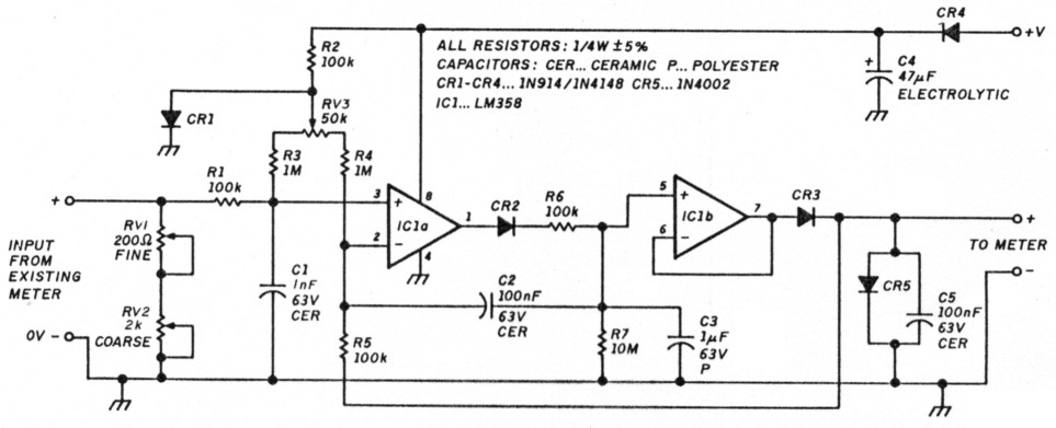
Figure 1 - Schematic of the PEP measuring add-In circuit.
Construction
The module can be constructed from readily available components on a small pc board (the commercial version` measures 55 x 30 mm), which can be mounted inside an existing RF-power/VSWR instrument. It may be fixed there with BluTackTM or a bolt, spacer, and nut arrangement, but do so only after calibration. Placement is not critical, except where the SWR instrument is combined with an antenna tuner; in that case the module should be placed away from and shielded from the strong RF fields which exist around tuner coils, capacitors, and their leads.
Interconnections
Undo both leads from the moving coil meter (only from the forward power meter if there are two). Check that the negative lead is grounded; in most instruments It is, but you can find the odd one where the positive lead is grounded, and this has consequences when supplying power to the module. Now ascertain that the meter resistance falls within the range of RV1 + RV2, which is 0 to 2200 ohms. All commercial VSWR meters I have encountered so far do, but some homebrew models using meters with 100 µA or less full scale deflection do not. In that case, make RV2 10 k.
Next, connect the former meter leads to the input terminals of the module and the module's output to the meter, carefully preserving polarities. A DPDT switch or PTT operated relay can be inserted to switch the PEP module in and out for SSB and other modes, respectively. Another method of reducing the peak holding feature of the module is to reduce R7, say by switching a 220-k resistor across it.
Power, anywhere from 4 to 25 volts DC at little more than 1 mA, must now be connected. If the negative meter lead was found to be grounded, a suitable voltage source, say 9 or 13.8 volts that is "on" when transmitting, can be found on the back of most transceivers. Use a single wire to connect that voltage, preferably through a 2700-ohm current-limiting resistor, to the positive terminal on the module. The coax shield will take care of the negative return.
In the rare case where the positive meter terminal is found to be grounded, a floating power supply must be used. In either case, three DuracellTM pen light cells would typically last nine months if left on continuously, or for years if switched on only when used. In all of the following adjustments, remember that the meter will travel upscale rapidly, but settle back slowly. Do wait for the meter to settle before reading.
First, the op amp offsets must be balanced out. For the commercial module this was done at the factory and RV3 was sealed. If you have built your own, or must replace the LM358 for any reason, a procedure is suggested below. A small positive meter reading with zero input is not an indication of an offset error and upscale readings will be correct.
Next, a calibration level must be established. With the PEP module out of the circuit, your transmitter in a constant carrier mode (CW, FM), and your SWR meter between the transmitter and a dummy load, pass some RF power through the meter. Increase the output to where a stable forward power reading (preferably over half scale) is obtained. Make careful note of the power reading and do not change the transmitter power setting until calibration is complete. Now reconnect the PEP module, set RV1 and RV2 to zero (fully CCW), apply DC power to it, and switch the transmitter back on at the power setting previously established as calibration level. Advance the "fine" preset RV1. If, with RV1, you can exceed the calibration reading previously noted, adjust to this reading. If the meter does not rise far enough upscale, set RV1 to about mid-travel and slowly advance the "course" preset to the calibration reading. RV1 will now allow more precise adjustment.
This calibration makes sure that RV1+RV2 presents the same load to the SWR instrument as the moving coil instrument previously did, so the input voltage to the module is unchanged. The module has exactly unity gain, so this voltage is repeated at the output, i.e., across the meter. Consequently the original meter calibration, nonlinearities and all, remains unchanged. On fast peaks, however, such as are encountered when speaking on SSB, the module will hold a peak long enough for the meter to rise to it and for you to check it.
Part list
| Capacitors | |
| C1 | 1 nF, 63 volts ceramic |
| C2, C5 | 100 nF, 63 volts ceramic |
| C3 | 1µF, 63 volts polyester |
| C4 | 47µF, 16 volts DC electrolytic |
| Diodes | |
| CR1-CR4 | 1N914/1N4148 |
| CR5 | 1N4002 |
| IC1 | LM358 |
| Resistors | |
| R1, R2, R5, R6 | 100 k, 5 percent, ¼ watt |
| R3, R4 | 1 meg, 5 percent, ¼ watt |
| R7 | 10 meg, 5 percent, ¼ watt |
| RV1 | 200 ohm |
| RV2 | 2 k |
| RV3 | 50 k |
Results
The results will probably surprise you. Without the module, normal speech will show peak meter readings of, say 30 percent of what an oscilloscope would indicate. With the module, it's 100 percent. A whistle, without the module, will show 80 or 90 percent, not 100 percent. Another interesting example is produced by tapping the mic with a pencil. The unmodified meter will show no reading, but with the module, full power will be indicated. MiGW4NAH, By John Fielden.