Home - Techniek - Electronica - Radiotechniek - Radio amateur bladen - Ham radio - 160 meter antenna problems and solutions
The quarter-wave Marconi working against ground is a popular and inexpensive antenna for 160 meters. A lot of newcomers to the band favor this simple antenna because it's easy to put up, it isn't too big, and it works.
I erected such an antenna a few years ago. I had an enjoyable time and worked a lot of stations on 160, but the signal reports I received weren't very ego building. Worst of all, many of the local 160-meter crowd were working DX I couldn't even hear! That was a bad sign. It meant that something had to be done about the antenna. I couldn't go to a vertical, and the position of the house on the lot precluded putting more wire up in the air. I had to make do with what I had.
The Marconi installation is shown in Figure 1. It would have been nice to get the flat top higher in the air, but that was impossible. Because I couldn't use a bigger antenna, I had to look elsewhere to improve my signal. Knowing that the transmitter power had to flow through the ground connection, this seemed a logical place to make an improvement in my signal. The ground consisted of the copper water system in the house plus one ground rod. Discussions with DXers on the band quickly convinced me that my ground wasn't as good as I'd hoped it would be. A lot of RF was being wasted in ground resistance. To monitor improvements, if any, I placed an RF ammeter in series with the antenna. With a power output of 80 watts, I logged 1.27-A antenna current. Ohm's law showed my antenna feedpoint resistance was about 49.6 ohms - a good match to my transceiver, even if DX performance was unimpressive.
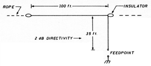
Fig. 1 - "Old Faithful" 160-meter Marconi antenna Is full of surprises that will fool the unwary user. Antenna is self-resonant at 1.85 MHz.
Improving the ground connection
I suspected that a lot of my output power wasn't going into the ground connection. Where else could it go? Perhaps it was going down the line cord and into the house wiring. Acting on this supposition, I wrapped the line cord around a ferrite rod and noticed the antenna current had now increased to 1.65 A. The feedpoint resistance of the antenna had dropped to 29.4 ohms. That indicated less ground loss. But now it was more difficult to match the antenna to the transceiver. I needed an antenna matching unit to achieve a 50-ohm interface.
My next step was to add two quarter-wave radials to the system. These wires ran about a foot above the ground and wound in and out through the shrubbery in the yard. It was the best I could do. Unfortunately, there was no room to add additional radials. I had to be content with what I had. The radials brought the antenna current up to 1.82 A. This was another step in the right direction. Now the computed feed-point resistance of the antenna was about 24.2 ohms.
There seemed to be a modest improvement in the antenna. I now found I could work some DX. Mine wasn't the loudest signal on the band, but the little antenna provided a lot of fun when the DX guns were occupied elsewhere. However, a nagging thought remained in the back of my mind. How efficient was the antenna? Had I really conquered the ground loss problem?
Computer analysis of the antenna
I didn't do much more with the antenna installation, and during the warm summer months I lost interest in 160-meter operation. But last fall I decided to get back on the band. Now I was able to analyze the antenna with the new K6STI computer program discussed in my last column .1 The analysis revealed that the true feedpoint resistance of my antenna over typical soil in this location was only 7.8 ohms! Because my measurement of antenna current indicated a feedpoint resistance of about 24.2 ohms, the inescapable conclusion was that the difference between the two figures (16.4 ohms) represented ground loss. My antenna efficiency was only about 32 percent! That meant that out of 80 watts, I was radiating only about 25 watts. The rest of my power (55 watts) was just warming the ground.
This also meant that I suffered about 4-dB signal loss in reception. No wonder I couldn't hear some of the weak DX on the band!
The solution: the folded Marconi antenna
In early spring I decided to change the single wire Marconi antenna to a folded system using two parallel wires (Figure 2). One wire was fed and the other returned to the ground connection. This provided an impedance step-up of four, and allowed an improved value of radiation resistance of 7.8 x 4, or 31.2 ohms. The ground resistance remained the same value as before (16.4 ohms), indicating that antenna efficiency was now about 66 percent. I had picked up 3 dB in transmitted power and had gained 3 dB in signal reception! Not a bad improvement for substituting 300-ohm ribbon line for the no. 14 wire in the antenna.
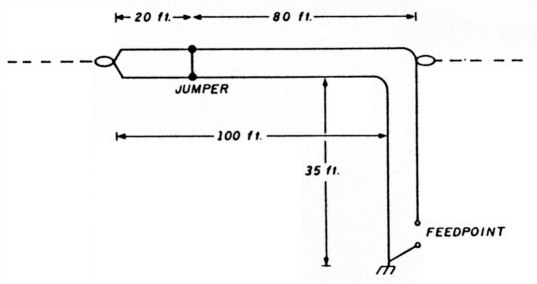
Fig. 2 - "Twin-lead" Marconi antenna. TV-type 300-ohm line is shorted 20 feet from end to account for velocity factor of line.
My final idea was to go to a three-wire folded antenna, which would provide an impedance step-up of about 11:1 (Figure 3). The antenna feedpoint resistance would then be 7.8 x 11, or 85.8 ohms. With 16.4 ohms ground resistance (which I didn't seem to be able to eliminate), the overall antenna efficiency rose to 84 percent! The small series of improvements gave me nearly 4-dB boost in transmission and reception at little cost. (That's an increase in power ratio of 2.51:1)
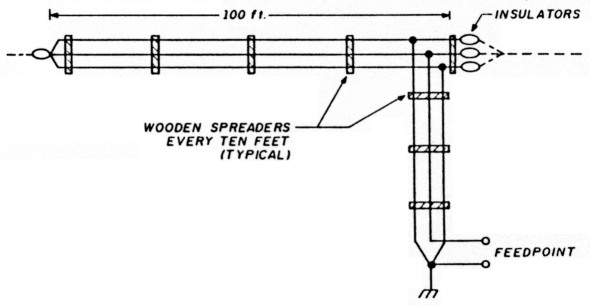
Fig. 3 - Three-wire Marconi provides high value of feedpoint resistance. If outer wires had half the diameter of the inner fed wire, the impedance step up would have been 9:1.
As I had no three-wire conductor on hand, I made one out of three no. 14 wires spaced 1 inch apart with a number of 4 inch long wooden spreaders. The assembly was a rat's nest on the ground but it straightened out when I got it up in the air and under tension.
A final run of the computer program showed that the Marconi exhibited about 3-dB directivity in the direction of feed, as Marconi had predicted long ago. In addition, the computer showed that the greater the length of the vertical portion of the Marconi, as compared with the horizontal section, the greater the feedpoint resistance. The limit, of course, is when the whole antenna is vertical. A single conductor has a feedpoint resistance of about 37 ohms (Figure 4).
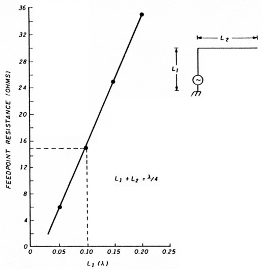
Fig. 4 - Bent-wire Marconi has low feedpoint resistance, depending on ratio of L1 to L2. When L1 is 0.1 wavelength, for example, feedpoint resistance is about 15 ohms.
How were my operating results? Much, much improved over the original design. At times, I even had DX stations answer my CQ. WOW!
Running the MN antenna program
Last month I explained the technique of preparing antenna data for inclusion in K6STI's antenna analysis program.(1) The discussion covered program theory, the coordinate system used, and wire, segment pulses, and sources. All of this information is placed in a special format and input to the computer. The antenna in question may be modeled in free space or above ground. The program lets you specify ground conductivity in the area of the antenna. I model antennas in free space as the program runs more quickly. Elevation plots for antennas above ground are available in many handbooks. However, the books can't show the effect of lossy ground on the elevation patterns. This can be very pronounced, and isn't often something you can figure out intuitively. Thus, after the antenna is modeled in free space with satisfactory results, it's a good idea to run it again over simulated ground. Your local conductivity factor will give you an insight into the reflection gain.
Modeling a sample antenna
As a working example, I'll discuss a popular 20-meter, three-element beam. The design is shown in Figure 5. The antenna is built on a 22-foot boom. Elements are assumed to be 1 inch in diameter. (Element diameter and taper will be discussed in my next column.)
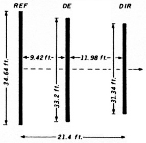
Fig. 5 - Three-element 20-meter Yagi. Design frequency is 14.175 MHz.
While linear element dimensions are shown, the MN program requires information in a different form. The tip position of all elements is expressed in X-Y-Z Cartesian coordinates. (Because the antenna is only two dimensional, the Z coordinates are zero.) The appropriate X-Y-Z data for this beam, plus other required information, are shown in Table 1.
| Three-element 20-Meter Yagi | |||
| 14.175 MHz Free Space 3 wires, feet | |||
| 10 | -10.7,-17.32,0 | -10.7,17.32,0 | 0.083 |
| 10 | -1.28,-16.6,0 | -1.28,166.0 | 0.083 |
| 10 | 10.7,-15.67,0 | 10.7,15.67,0 | 0.083 |
| 1 source | |||
| 14 | |||
| 0 | |||
To create an antenna file, you need a text editor or word processor. The MN package includes a text editor called TED. This is a short program and works much in the manner of WordStar'. You can use other programs, like EDLIN, if you wish. But TED does the job quickly and easily.
Once the information has been placed in the word processor in the proper form, give the data a name and an extension (.ANT), and the file is entered into the antenna program. In this case, the name used is 3LYAGI.ANT.
After you view the antenna file for accuracy, start the computation to determine the gain, front-to-back ratio, and input resistance (impedance) by giving the command "G". In this example (using a math coprocessor) the matrix fill time is 21 seconds. The computed antenna information is shown in Table 2.
| Matrix Fill Time | 0:21 |
| Matrix Factor Time | 0:02 |
| Impedance | 22.3 -j 3.9 ohms |
| SWR | 2.26 for Z = 50 ohms |
| Forward Gain | 5.95 dBd |
| F/B | 31.83 dB |
| Maximum Sidelobe | 26.98 dB down at 124x Azimuth |
| Azimuth Beamwidth | 63% |
| Elevation Beamwidth | 100% |
This particular antenna is designed for good gain with a high degree of front-to-back ratio. About 1 dB of the maximum possible gain is sacrificed to achieve this favorable ratio. Input impedance is good, with the driven element being slightly short for the design frequency of 14.175 MHz.
The last step in the program is to display the directive pattern. If you want to print it, you'll need a dot matrix printer (see Figure 6). And there you have it! All of this vital data is derived without cutting a single piece of aluminum or climbing even one foot up a tower!
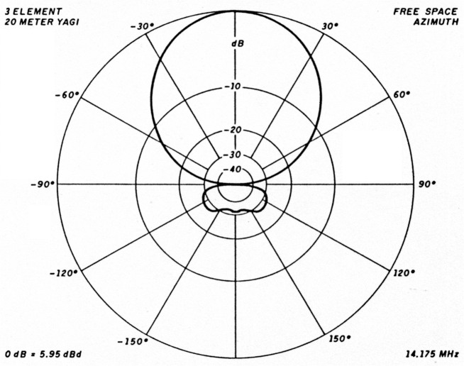
Fig. 6 - Azimuth pattern of 20-meter Yagi combines good gain with excellent front-to-back ratio.
The antenna file
The MN program has a library of many different antenna files which you can examine before you input your own design. It's a good idea to examine these files to get the "feel" of how the program works and how the data is input to the program. Start with a simple antenna, like a dipole or two-element Yagi. Note how the XYZ coordinates are derived and pay attention to the spaces between statements, letters, and numbers within the individual lines. If results seem odd, examine the RUN file to see if you have allocated pulses and the source properly. You'll find that reviewing the antennas in the file, before you run your own program, pays big dividends. MN has built-in prompts which lead you step by step to the conclusion. You may be dismayed at some of the ego-deflating gain figures for beam antennas provided by MN which contradict highly touted figures given by some beam antenna manufacturers, but that's the way it is.
Next month I'll review the Yagi optimizer program which lets you manipulate the dimensions of your antenna and see what happens when you change length, spacing, and taper of Yagi antennas. Stay tuned!
The dead band quiz
Thanks to the following additional readers who responded to my problem about the snowplow. (See last month's column for the solution.) They are: AC5P, KE2MO, N6SVI, NG5F, WY7U/4, James Conley (no call given), W6MUR, WA7HVT, and K4KQS.
Some readers have requested a "literary quiz" instead of a mathematical-type problem. So here are two little quizzes to whet your appetite:
"Remain on patrol in vicinity of Rockall"
This unusual signal was sent by whom to whom? What was the approximate date the signal was sent, and what was the significance? What, or who, is Rockall? What is the story and who is the author?
The second quiz concerns a popular TV show now in rerun. Who said the following and under what circumstances?
"Brain! Brain! What is brain?"
Good luck and see you down the log. Written replies to these little brain teasers will be acknowledged in this column.
References
- Bill Orr, W6SAI, "Ham Radio Techniques: The MN Analysis Program That was then this is now)," Ham Radio. February 1990, page 34.
W6SAI, Bill Orr.