Home - Techniek - Electronica - Radiotechniek - Radio amateur bladen - QST - A simple "Wien bridge" audio oscillator
Good waveform and uniform output amplitude.
When considering building an audio oscillator it pays to think twice. There are three major types of audio oscillators: the LC oscillator with which we are familiar from work with r.f., the beat-frequency oscillator, and the resistance-capacitance tuned osdillator. The LC oscillator will produce a very satisfactory note for code-practice work and the like, but for test purposes its waveform usually leaves much to be desired; also, when the frequency is varied the amplitude does not remain constant, and the necessary components for tuning are not conveniently obtainable. The beat-frequency oscillator is very satisfactory in operation when properly designed electrically and mechanically, but the fine points of this design are rather subtle and not readily understood by most of us. To get proper frequency spread with a beat oscillator it is necessary to use a peculiar condenser-plate shape (which is very hard to obtain commercially), and there remains the constant headache of properly setting the oscillator to zero.
But the RC oscillators suffer from few of these disadvantages. The phase-shift oscillator is a very pretty little device that will be appreciated by anyone having an understanding of RC theory, and its one-tube simplicity would recommend it to one and all were it not that there is no immediately practical way of regulating its output. But in the so-called Wien bridge(1) oscillators even this objection is overcome.
The Wien bridge oscillator has long been a mystery to most of us and hence is in our minds surrounded with an aura of superstitious awe. Some of us have built them with very unsatisfactory results, and we have the feeling that choice of components or arrangement must be far too critical. It is unfortunate, too, that much has appeared in the literature that is confusing, including circuits that look as though an engineer would be needed to untangle them.
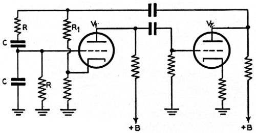
Fig. 1. Essentials of the "Wien bridge" oscillator circuit. Frequency is determined by the values of R and C; oscillation amplitude by the proportion of the output voltage fed back to the cathode of V1.
The Wien bridge oscillator need be only a very simple device, as shown in Fig. 1. It would be hard to improve on at least one explanation(2) of the operation of this circuit, but a little simplification might be to the point. The two-tube resistance-coupled amplifier is straightforward enough, and it will be seen that we carry the output back to the input. This output is fed to the cathode of V1 through a voltage divider, and this feed-back is degenerative and constant with frequency. But we also carry it to the grid through the RC network. Now this feed-back voltage at the grid is regenerative and is different with different frequencies, and varies also in phase. Fig. 2-A gives a rough idea of this characteristic. Again referring to Fig. 1, it will be seen that to make the circuit oscillate it will be necessary to introduce a signal between grid and cathode of V1 in the same phase as the voltage at the plate of V2 and of sufficient amplitude (output voltage/amplifier gain) to maintain oscillation. The voltage between grid and cathode of V1 will be equal to the algebraic sum of the voltages on the grid and the cathode with respect to ground. Now when we are far from the frequency of oscillation the net voltage between the grid and cathode will be opposite in phase to that necessary for oscillation; that is, the negative feed-back will predominate. This is because the regenerative signal to the grid is small and is also in the wrong phase (by almost ninety degrees) to be a significant factor in the algebraic sum. Only at "resonance" will the phase of the signal at the grid be exactly opposite to that on the cathode, and only then - if the degenerative voltage fed back to the cathode is properly adjusted - will there be sufficient net regenerative feed-back to make the circuit oscillate. Fig. 2-B shows the effective regenerative voltage fed to the grid at a level just below oscillation. Comparing this with Fig. 2-A gives some indication of the importance of the phase relationship in the algebraic sum.
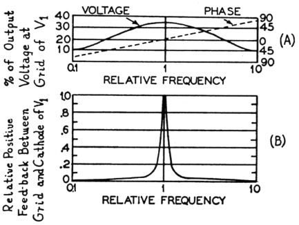
Fig. 2. (A) Relative amplitude and phase of the positive feed-back voltage between the grid of V1 and ground, with reference to output voltage of V2.
(B) Effective positive feed-back voltage between grid and cathode of V1 for the same conditions as in A.
It will now be seen that the circuit is critical in just two respects; the constants of the frequency-determining circuit and the amount of degenerative feed-back. The amplifier can he anything so long as it has negligible phase shift over the range to be used and provided that it can drive the low impedance offered by the degenerative voltage divider and the Wien bridge network. If we replace the lower member of the degenerative voltage divider with a filament-type bulb whose resistance will increase as the oscillation amplitude increases, thereby increasing the proportion of the feed-back voltage present at the cathode and stabilizing the oscillation level, we can set the degeneration level once (with R1) and forget about it.
Frequency determination
The frequency of oscillation is determined by the values of R and C, and
![]()
in the case where the Rs are equal and the Cs are equal. It doesn't matter from the standpoint of waveform exactly what proportion the Rs and Cs bear one another (because the circuit will balance with nearly any values) just so long as when the values are changed to vary the frequency they are changed proportionally. On this point depends consistency of waveform and amplitude with change of frequency, and this is where most builders of Wien bridge oscillators fall by the wayside. When tuning is done by means of a variable condenser it is essential that the two sections track, at least proportionately, when stray capacitances, particularly those from rotor to ground, are considered. And when resistors are switched, or variable resistors are used, the members of each pair must maintain the same proportion to one another. It will be seen that the easiest solution to the problem is to keep the Cs and Rs equal. The only other point to be remembered is that the Rs should be kept high enough (a thousand ohms or so) so that the Wien bridge network does not load the amplifier too heavily.
The problem of how to tune a Wien bridge oscillator is an interesting one. Most of those in recent literature have been modeled after the Hewlett-Packard oscillators and call for four-gang condensers. A four-gang condenser wired as two-gang will provide a capacitance range and hence a frequency range of over ten-to-one, which permits the audio band to be split up into decades. Since four-gang condensers are not readily available a two-gang condenser may be used instead, and will provide a frequency range of about 3-to-1, or two ranges per decade.(3) This results in better bandspread, although it does require more bands to cover the audio spectrum. Such an arrangement is shown in Fig. 3, and may be substituted for the frequency-determining network in any circuit calling for a four-gang condenser.
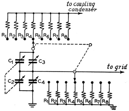
Fig. 3. RC network for continuous frequency coverage from 15 cycles to 150 kilocycles per second. C1 and C2 are sections of a two-gang 450 pF per section variable condenser. C3 and C4 are 150 pF trimmers. The following table gives resistor values and frequency ranges:
| Resistors | Values | Frequency range |
|---|---|---|
| R1 | 20 MΩ | 15 to 50 cycles |
| R2 | 6 MΩ | 50 to 150 cycles |
| R3 | 2 MΩ | 150 to 500 cycles |
| R4 | 600 kΩ | 500 to 1500 cycles |
| R5 | 200 kΩ | 1.5 to 5 kc. |
| R6 | 60 kΩ | 5 to 15 kc. |
| R7 | 20 kΩ | 15 to 50 kc. |
| R8 | 6 kΩ | 50 to 150 kc. |
Tuning by use of ganged potentiometers is perfectly satisfactory provided that the pots can be made to track. This throws out any thought of using carbon pots; they have been mentioned in the literature, but their use is incompatible with consistency of waveform and amplitude. Wire-wound pots, particularly of the type made by General Radio, are satisfactory when ganged and can be made to cover frequency ranges of onehundred-to-one or even more. Unfor unately such pots are not usually available in any but a linear taper so that the second decade is seriously crowded. This is because the frequency curve is linear with respect to resistance.
Spot frequencies
One of the most useful tuning systems is a switching arrangement that provides spot frequencies at three or more points per decade throughout the audio spectrum. This is very convenient for measuring amplifier frequency response because it gives you your plot points without having to tune them. It is also handy for waveform and distortion measurements. Such a system can be very compact, mechanically, and one swing of the switch carries from one end of the band to the other. The only application where it is less satisfactory than the continuously-variable type is in running response curves on highly-selective audio circuits and in checking resonance points. For this purpose, however, the scheme of Fig. 3 with its good band- spread will be far more satisfactory than the conventional oscillator using a four-gang condenser and a frequency range of ten-to-one.
Fig. 4 shows an audio oscillator using this switch-tune system, together with a slightly unconventional but completely satisfactory power supply which was used in it. A 6SN7 provides the two triodes which are necessary for the oscillator, and a 6H6 is used as a half-wave voltage doubler to provide the 165 volt "B" supply needed by the oscillator. Two filament transformers are used back-to-back to provide filament voltage and line isolation for the "B" supply. The first transformer has a 2 ampere winding to supply filaments as well as to drive the second (1 ampere) "plate transformer." Connecting the pilot light across only half of the 6.3 volt winding eliminates annoying glare while still providing ample visibility. With a two-pole ten-position switch the frequency range is 20 to 20,000 cycles. One of the little Mallory wafer switches (2 pole, 9 position) may be used at the sacrifice of one frequency. So long as the members of each pair of resistors are equal the thing will work perfectly; the accuracy of frequency will be as good as the accuracy of resistance. It is suggested that the resistors be checked on a bridge, although an ohmmeter will serve to make sure they are equal. The feed-back control is adjusted for maximum output commensurate with waveform, as observed on a scope. If one is not available an a.c. thousand-ohm-per-volt meter may be connected to the output (frequency set at 100 cycles and both attenuators all the way up) and the amplitude set at about one-half maximum.
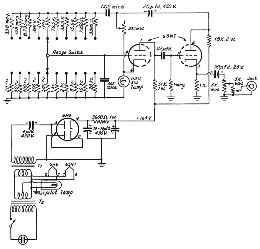
Fig. 4. Circuit diagram of oscillator with 10 spot frequencies in the audio range, and power supply. Resistor values (upper row) are duplicated in the lower row to give the stated frequency.
Output is taken from the amplifier cathode so that loading will not affect oscillation. The amplitude will be about two-volts peak. A double attenuator was used so as to make possible vernier adjustment of low levels for speech-amplifier adjustment and the like.
An alternative arrangement is shown in Fig. 5, using a power amplifier if more output is desired.
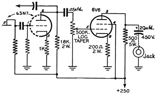
Fig. 5. Suggested amplifier circuit for increasing the output voltage from the oscillator.
This oscillator was built inside a 7 × 9 × 2 inch chassis with the controls projecting through the chassis face. Fig. 6 shows the approximate mechanical arrangement. The two tubes and the double ten-ad. condenser are mounted on a small bracket and ventilating holes are cut to keep them cool. The 3 watt bulb (which, contrary to popular superstition, does not light) and the feedback adjustment resistor are both inside. When a standard bottom plate is screwed on, the unit is a very handy thing to have on the bench.
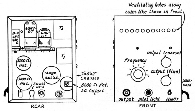
Fig. 6. Layout of the 10-frequency oscillator circuit given in Fig. 4. The unit can be built inside a 7 × 9 × 2 inch chassis.
Notes
- The circuit discussed is not truly a Wien bridge oscillator. We realize this, but bow to popular usage which has named this oscillator because of the resemblance between its frequency-determining circuit and that of the Wien bridge.
- Terman, Radio Engineers' Handbook, page 505. That ever-useful device, the audio-frequency oscillator, in simple and reliable form. Where continuous tuning is not required, any desired number of spot frequencies can be provided by a selection of resistors and a multiposition switch.
- By the exercise of extreme care in regard to stray capacitance and the like it is possible to tune this type oscillator over a range of ten-one-to with a two-gang condenser. This requires that the total capacitance from stator to ground does not exceed about 40 pF. This care is justified when it is desired to build an oscillator of wide frequency range into a very small space.
Howard T. Sterling.