Home - Techniek - Electronica - Radiotechniek - Radio amateur bladen - QST - A soup-can wavemeter for the 23 cm band
Frequency and field-strength measurements at low cost.
For the experimenter, the 23 cm band (1215-1295 Mc.) probably offers more possibilities than any of the other amateur u.h.f. assignments. But before you can use the band you need to know how to find it. This article tells how to make a 23 cm wavemeter that also can be used for checking antenna patterns - at little more cost than the price of a 1 mA meter which you've probably got already. No special tools - and no machining!
One of the most interesting of the new ultrahigh-frequency bands available to the ham is the 80 Mc. spread located between 1215-1295 Mc. This 23 cm band is located in the radio spectrum at just about the point where the operating ranges of three tube types - magnetrons, klystrons, and lighthouse triodes - overlap, which is fortunate because it offers the opportunity to get acquainted with three different u.h.f. operating techniques. However, 23 cm. is a sufficiently short wavelength to permit the use of highly-directional antenna structures, thereby effectively increasing the transmitter power.
Before attempting to set up a station on this band, it is wise to become familiar with the circuit components used at these wavelengths. It is obvious that resonant circuits using coils and condensers would be impracticably small.
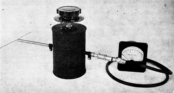
Disguised in black crackle, the tin-can wavemeter has a very professional appearance. This is the unit complete with dipole antenna, crystal detector and indicating meter.
Instead, short sections of transmission lines whose principal dimensions may be a large fraction of the wavelength are used. Transmission lines in the ultrahigh and superhigh regions are either coaxial or waveguide systems where the traveling energy is contained entirely within a metallic enclosure. Resonant circuits made from sections of these lines have decided advantages, in that they provide nearly perfect shielding and can have a much higher Q than is possible with ordinary coil-condenser combinations.
The experimenter will want to familiarize himself with at least one type of resonant circuit or "resonator" which tunes over the 23 cm band. The simplest and probably the most useful gadget for early work at these frequencies is a wave-meter. The photograph shows one that can be made from parts found in every household. (Notice I said household and not ham shack! This is because the wavemeter is made from tin cans, copper pipe, and some nuts and bolts.) It can be used as a relative field-strength meter for taking antenna-pattern measurements as well as for frequency measurement.
The wavemeter is essentially a quarter-wave section of coaxial line short-circuited at one end. By adjusting the length of the center conductor the resonant frequency can be varied over the 23 cm band.
As shown in Fig. 1, the magnetic lines of force set up inside the enclosure are circular about the axis, while the electric lines of force are radial along the length of the center post and then distort at its free end to fill the space beneath it. A single-turn coupling loop is used to feed energy into the wavemeter through a short coaxial line. Another single-turn coupling loop is used to extract energy from the resonator to feed a crystal or other detecting device, as shown in the equivalent circuit, Fig. 2. This method of coupling is similar to the standard ham practice of "link" coupling between tuned circuits. Since the loops depend upon magnetic coupling to transfer energy, it is necessary that they be oriented properly within the resonator to link some of the magnetic lines of force. Maximum coupling is obtained when the loops are entirely within the resonator and their." windows" are parallel to the axis, as shown dotted in Fig. 1. Either rotating or withdrawing the loops will reduce the coupling.
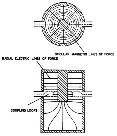
Fig. 1. Electric- and magnetic-field configuration inside the resonator.
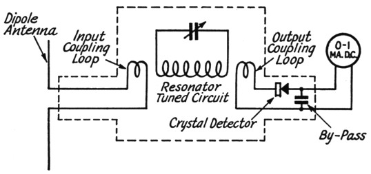
Fig. 2. The wavemeter circuit in terms of low-frequency symbols. The actual tuned circuit is a coaxial resonator of the type shown in Fig. 1.
How to build it
The construction of the wavemeter is shown in cross-section in Fig. 3, while an "exploded" view of the various parts in their relative positions is given in the photograph. Notice that the adjustable section of the center conductor does not make physical contact with the larger diameter pipe, thus avoiding troublesome finger contacts. However, the opening between the two appears as a short-circuit to u.h.f. waves because the distance from this gap along the center pipe and down between the two cans to the shorting ring is an electrical half wavelength. One of the properties of transmission lines is that an impedance seen at a particular point is repeated every half wavelength along the line. Since there is an electrical short-circuit between the inner and outer cans at the soldered ring, then one-half wavelength away, at the opening between the two pipes, another short-circuit appears. The large can acts as the outer conductor for a portion of the half-wavelength line, as well as providing protection to prevent denting or distorting the inner can (the actual resonator) after calibration.
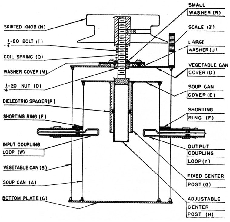
Fig. 3. Cross-section drawing of the assembled wavemeter. Letters in parentheses correspond to the lettered parts in the photograph.
The tools necessary for building the wavemeter are familiar, and include tin snips, hacksaw, files, a soldering iron, and a drill. A 4-40 tap and a drill press equipped with a flycutter will be of help in the preparation of the parts, but are not essential. A 1/8 to ¼ inch thick steel plate about 6 inches square is very useful in the assembly soldering operations on the kitchen stove.
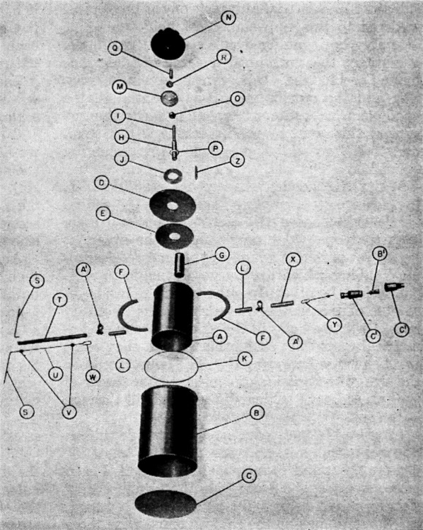
Exploded view of the parts entering into the wavemeter assembly. Tin snips, a hacksaw, files and a soldering iron are the principal tools required.
Choose a clean, undented soup can (Part A) of the Campbell or Heinz variety, 2_5/8 inch diameter rim by 4 inches long, and remove the top and bottom with a rotary-type can opener. This operation produces smooth edges and leaves a strong rim. Now choose a medium-sized vegetable can (B), 3_3/8 inch diameter rim by 4½ inches long, and remove the top and bottom as before. Be sure both cans have a bright finish and not the dark wartime finish, because it is much easier to solder to the tinned surface. Clean the cans thoroughly with hot water and soap before attempting to do any soldering.
From 1/32 inch thick sheet brass or copper cut two disks (C and D) 3_7/16 inches in diameter. These disks should be a trifle larger than the top of the vegetable can to allow space for soldering. Cut another disk (E) 2_11/16 inches in diameter, which again is slightly larger than the top of the soup can. Drill or punch a %-inch diameter hole in the center of the small disk (E) and in one of the larger disks (D). A ¾ inch socket punch for filter condensers is useful here. Next, cut a ring from the winch sheet material with an inside diameter equal to the outside dimension (not the rim) of the soup can, and an outside diameter equal to the inside dimension of the rim of the vegetable can. With the tin snips cut this ring into two halfring segments (F). When these two segments are soldered in place between the two cans, as shown in Fig. 3, they form the actual short-circuit at one end of the half-wavelength line mentioned earlier.
Obtain a piece of brass pipe having an outside diameter of ¾ inch with a wall thickness of 1/16 inch. Cut and file the ends square to a final length of 1¾ inches (G). Be sure the inside surface is smooth and clean. Take a ½ inch outside diameter brass pipe (H) and cut it to 2_1/16 inches in length. Solder a scrap of the 4 inch sheet stock across one end and file smooth, making a metallic cover for the end of the tubing. Fasten the head of a two inch ¼-20 brass fluster or hex-head machine screw (I) into the other end either with small screws or by soldering, allowing the threaded portion to protrude from the pipe. (It may be necessary to cut additional threads up to the base of the head.) Be sure the machine screw is in exact alignment with the axis of the pipe, as this assembly is the adjustable center-conductor section.
With a piece of fine emery cloth polish the small disk (E) and the ¾-inch diameter pipe (G). Tin the inner and outer edges (one side only) of the disk and around one edge of the pipe with the soldering iron (a 150-200 watt iron is desirable). Rosin-core solder could be used, but plain solder and an acid flux will produce better mechanical results. It is important to clean off all traces of the acid flux after soldering, however, to prevent corrosion. Now tin the top and bottom rims of the two cans to insure a clean soldering surface and a good electrical bond between the rims and the insides of the cans. Some cans have a sealing gasket under the rim, so this solder bond is necessary. Place the 6 × 6 inch steel plate on the kitchen-stove burner and heat until it browns a piece of paper. Drop the small disk (tinned side up) on the plate and stand the ¾ inch pipe in the hole. Add slightly more heat to the plate until the tinned sections turn shiny. Touch the disk-pipe joint with some solder until it flows in a clean ring around the pipe. Now place the soup can (A) on the disk, and solder the outer edge in a similar manner. When the joints are complete, turn off the heat and allow the whole assembly to cool slowly. Do not attempt to move anything on the plate during this cooling process!
Measure down 1½ inches from the disk on the outside of the soup can and tin a strip ½ inch wide around its circumference with the soldering iron. Emery the two half-ring segments (F) and tin their inner and outer edges. Solder these pieces to the soup can at this tinned strip. Also solder the places where the ring was cut in half. When the segments are held in place, a solid bond can be obtained by holding the iron against the joint and slowly moving it around the can.
Polish the top disk (D), and solder a 1½ inch brass washer about 3 inch thick (J) at its center. Be sure the washer is in the middle, and has a hole at least as large as the inside diameter of the pipe soldered to the soup can. Drill and tap three 4-40 holes 120 degrees apart into the washer-disk assembly on a 1_1/8 inch diameter circle. If no tap is available, drill clearance holes through the washer and solder brass nuts to the underside of the disk.
Tin a ¼ to 3/8 inch wide strip two inches down from one edge on the inside of the vegetable can (B). Slide the soup-can assembly into the vegetable can so that the ring coincides with the tinned strip and the open edges of the two cans are flush. Put several wooden spacers between the cans to keep them aligned. Make a thin ring of solder (K) and place it around the tinned area inside the large can so that it rests on the brass piece soldered to the soup can. Now hold the whole assembly horizontally over a medium gas flame, and rotate the work until the ring of solder has melted and formed a solid joint between the brass ring and the outside can. It is essential that a good electrical contact be made between the two cans at this point by the brass ring (F). A small blowtorch would be useful for this soldering operation.
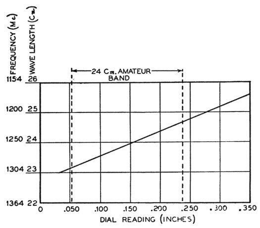
Fig. 4. Typical calibration curve. It will not apply to the one you build, but your curve should be similar.
While the wooden spacers are still in place, the holes for the coupling-loop guides (L) should be drilled. Choose two sizes of copper tubing such that one slides snugly inside the other, or better yet purchase two pieces of brass "telescoping" tubing which are purposely made to slide one inside the other. In either case the inside diameter of the smaller piece should be about 14 inch. Drill two holes in the sides of the cans diametrically opposite each other so that they come just below the brass ring (F). The holes should be the size of the outside dimension of the larger of the two pieces of tubing. Be sure to drill through both cans.
Cut two 1_1/8 inch lengths of this outside tubing. Square both ends and saw six thin slots 60 degrees apart and 3/8 inch deep in one end of each piece. A wooden dowel inside the tubing during slotting might help. After polishing with emery, tin about ½ inch on the smooth ends. Slide these pieces (L) into the holes in the cans until the tinned ends are just flush with the inside of the soup can, and solder both inside and outside joints with the iron.
Remove the wooden spacers near the bottom of the assembly. With the upper spacers in place, solder the large, solid disk (C) to the bottoms of the cans, using the metal-plate-over-stoveburner technique. It is especially important that the soup can (A) make good contact with this bottom disk. Proper tinning of the cans and the disk will insure a good joint. Next, remove the upper spacers and solder the top disk (D) to the large can, with the washer on the outside. Use a wooden dowel to align the washer with the pipe (G) inside the small can. After "tacking" the disk in place with the soldering iron, the final soldering can be done on the plate. Allow time for the heat to flow through the disk to the joint, however.
On a 1¼ × 3/16 × 1/32 inch piece of sheet brass scratch lines at one end across the 3/16 inch face, 1/20 inch (0.050") apart. Ten or fifteen lines should be enough. Now bend the other end at right angles, making a 3/16 × 3/16 inch foot for the scale (Z). Solder the scale in an upright position on the top disk (D) along a radius at a distance from the center just slightly larger than the dial (N) you plan to use. India ink or black paint in the scratched lines will make them easier to read. A more elaborate scale can be made by taking a 3/16 inch diameter brass rod and cutting grooves around it 0.050 inch apart. Every fifth groove is cut wider to allow easy reading. Mill or file a flat section along the rod and stamp numerals at each wide line. Fill the grooves and numerals with white wax. A 4-40 thread at the base makes it easy to mount on the cover plate (D). The wavemeter in the illustration uses this type of scale.
Cut a brass disk (M) the size of the large washer (J), and drill a hole in its center to pass the machine bolt (I) fastened to the ½ inch pipe (H). Drill three holes spaced 120 degrees apart on a 1_1/8 inch diameter circle to pass the 4-40 screws. Solder a ¼-20 brass nut (0) to the underside of this disk (M) at its center.
About 1_1/8 inches down the ½ inch diameter pipe (H) used as the adjustable center conductor, build up several layers of coil dope or polystyrene tape about 3 inch wide. Build up enough to act as a dielectric spacer (P) between this pipe and the one inside the soup can. When the material becomes hard, shape it so that the adjustable section will turn inside the other pipe without wobbling. A ring of polystyrene or other good u.h.f. dielectric turned on a lathe is equally satisfactory.
Now thread the bolt into the nut and through the disk (M). Mount the whole unit in the resonator assembly, with the pipe going through the other center conductor (G). Fasten the brass disk, with the nut on the underside, to the washer (J) with three 4-40 machine screws. The bolt should now turn rather easily and without binding.
Make a coil spring (Q) of music wire (about 0.050" wire) with a one-inch free length and an inside diameter of 9 inch. Bend or grind the ends of the spring square, so that it stands up straight when placed on a flat surface. Slide a washer (R) over the bolt, add the spring (Q), and then fasten a regular dial to the end of the bolt. It is best to choose a fluted dial with a skirt or flange. For convenience in taking measurements it is desirable to make and label 50 lines on the skirt, spaced 7.2 degrees apart around its periphery. Each division is now 0.001 inch motion of the tuning member when using a ¼-20 bolt. A dial with 360 degrees marked on it would also be suitable. A fair approach to this can be achieved by taking two protractors and mounting them underneath but protruding beyond the skirt of the dial. The divisions on the dial together with the marks on the vertical scale mounted on the cover plate provide means for taking fairly accurate readings.
The pick-up antenna
It is necessary to make a simple antenna (S) that can be used to pick up signals from the transmitter. Cut a piece of the small or inner telescoping tubing (T) to a length of 5 inches. Pass a straight copper wire (U) (about No. 16) through its center using one or two polystyrene "beads" (V) to support it, making a small coaxial line. At one end of this line make a loop (W) about ½ inch long by ¼ inch wide, and solder its end into a small saw-cut in the edge of the tubing. Shape the loop and file the solder joint smooth so that it can slide through the larger tubing and into the resonator chamber. At the other end of this coaxial line bend the wire at right angles and cut it off at 2½ inches. Now solder another 2½ inch piece of wire to the tubing in the other direction, thus forming a doublet or "dipole" antenna (S).
Cut another piece of this tubing 1½ inches long (X) and make a similar loop (Y) at one end. Arrange the other end of this short coaxial section with a suitable fitting to connect to the particular type of crystal holder you have available. The holder should use the standard-type crystal cartridge (B') such as the 1N21 or 1N22 silicon detectors. The photograph shows a typical crystal holder (C1) which is made to couple to a Y4-inch coaxial fitting. If a crystal holder is not on hand, it is necessary to provide some means for connecting the crystal in series with the center conductor of this pick-up-loop section. (Do not solder to the crystal cartridge at all!) The cartridge should be entirely shielded, and polystyrene tape or other dielectric material should be wrapped around the large end to provide a capacitance to and yet prevent it from shorting to the outer conductor. A small 500 pF "button"-type condenser may be used as this by-pass capacitance. The indicating instrument (usually a 0-1 mA d.c. meter) is now connected between the large end of the crystal and the outer conductor. The small or pin end of the crystal connects to the inner conductor and completes the circuit both for r.f. and d.c. through the loop to the outer conductor. It is important to remember that there must be a low-resistance d.c. return path for the crystal current via the loop circuit, otherwise the meter will not read.
Put the antenna loop (W) into one side of the resonator and the crystal detector loop (Y) into the other side. Orient the loops so that they are in line with the axis of the wavemeter and are protruding part way into the inner can. Make some simple strap clamps (A') from the 1/32 inch sheet brass stock to go around the slotted sections of the loop guides to prevent the loops from sliding or turning after the unit has been calibrated. When the crystal and meter are connected, the wavemeter is ready for operation.
Adjusting & calibrating
Place the antenna in the field of a low-power 23 cm. transmitter, and slowly turn the dial of the wavemeter until a reading is obtained on the meter. If the meter goes off scale, back out or rotste the loops to reduce the coupling, and re-tune the resonator. Adjust the coupling until the meter reads about ½ to ¾ of full scale when placed several feet away from the transmitting antenna. Another way to reduce the coupling is to reduce the size of the loops. If the crystal is not very sensitive, a 100 µA meter may be needed.
The job of calibration comes next. Before going into this, however, it must be pointed out that the loops cannot be moved after calibration without spoiling the dial readings, so be sure they are adjusted to your satisfaction and then clamped in place before going further. The simplest method of calibration is to obtain readings on a previously-calibrated 24-cm. wavemeter. If this is not possible, it is then necessary to take the alternative step. Make a Lecher-wire system several wavelengths long (about one meter) with two parallel copper wires spaced % to 1 inch apart. Stretch them between two wooden posts or on a device like a bow. At one end connect the wires together and loosely couple this loop to the transmitter. Take a small dial lamp (2 to 6 volts, depending upon the transmitter power) with wires soldered to its terminals, and slide it along the transmission line. It will light at certain points and will go out altogether at others as it is slid along. Now loosely couple the wavemeter to the system and tune for a peak on the meter. Measure the distance (in centimeters) between two adjacent points where the bulb is extinguished, and this will be equal to one-half wavelength. The reading of the wavemeter dial now corresponds to the wavelength just measured. By repeating this procedure for several different wavelengths in the 24-em. band, calibration points for the wave-meter dial can be obtained. Refer to the ARRL Handbook for further information on using Lecher-wire systems.
It is quite useful to plot a graph of the dial readings against wavelength (or frequency) to simplify interpolation between the calibration points. To convert from wavelength to frequency use the following formula:
![]()
A typical calibration curve is shown in Fig. 4. If the dimensions of the wavemeter are followed rather closely, the slope or tuning rate of its calibration curve should be the same as the one illustrated. About five turns on the dial are required to cover the entire band of 80 Mc.
The Q of the experimental wavemeter was 850. Since Q is related to bandwidth by the following expression:
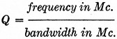
the bandwidth to the half-power points of the resonance curve was 1.48 Mc. for the soup-can wavemeter. It is possible to regard the bandwidth of this type of circuit in exactly the same manner as with low-frequency resonant circuits using conventional coils and condensers.
To dress up the appearance of the wavemeter a coat of black wrinkle paint provides a durable finish. Be careful not to get any paint on the inside where it could cause poor contacts, especially in the loop guides. Again it must be mentioned that moving either the loops or the location of the diaron the shaft will affect the calibration.
In general, the wavemeter is used with the dipole antenna to measure the frequency of an oscillator or to determine an antenna pattern. A small loop section similar to that on the crystal detector can be used, however, for coupling to a coaxial line input. If this is desired, it would be well to calibrate the wavemeter with the loop in place, and then make a dipole antenna which would couple to this loop section like ' a coaxial line. Either the antenna or a coaxial line can then be used on the input at will, without seriously affecting the calibration.
Frederic A. Jenks, W2MTH.