Home - Techniek - Electronica - Radiotechniek - Radio amateur bladen - QST - Keeping your harmonics at home
A discussion of the factors in harmonic generation and radiation.
For a time after the opening of the 80-meter band it began to look as though the ham that didn't have a harmonic report from the FCC was just waiting his turn like the ten little Indians in the nursery jingle. Certainly there was a lot of activity on 40! But some good will come of it if the situation focuses attention on the unnecessary radiations that plague our own operation as well as that of other services.
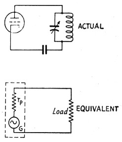
Fig. 1. The tube amplifier and its generator equivalent.
For years we have had a collection of nostrums for harmonic radiation, some of which seem to have acquired acceptance chiefly by repetition. For example: "Push-pull amplifiers have no even harmonics." Lots of hams believe it, although that particular theory was exploded by Uncle Jimmy way back in the early 30s - and despite the fact that users of push-pull amplifiers stand high in the list of ticket collectors. There are others, too, likewise based on a sound-enough idea, but with no data to prove whether or not they are effective. Among these are such things as reducing excitation to make the amplifier output "purer" and the use of high-C tank circuits for the same purpose. The whole subject seems to be enveloped in a vagueness that doesn't offer much help to the chap who's in trouble and wants to know how to get out.
A couple of things at least are clear: (1) Any power amplifier operated at reasonable efficiency - that is, beyond Class A conditions - will generate harmonics of appreciable amplitude. 12) On high frequencies an extremely small amount of radiated energy can put down a good readable signal hundreds and sometimes thousands of miles away. (3) Radiation can take place directly from transmitter tank circuits and wiring. (4) Or it can take place from the antenna. So the question of eliminating harmonic radiation is really three questions: How can the amount of harmonic generated by the transmitter be reduced? How can radiation from the transmitter itself be prevented? How can harmonics be kept from getting into the antenna system?
Excitation vs. harmonics
We have a means of getting at the answer to the first question by considering power-tube operation from the "equivalent generator" standpoint. The tube is replaced by a generator, G, having the same internal resistance, ri,, as the tube (see Fig. 1) and working into a load having the same characteristics as the plate tank circuit. (For the moment this load is assumed to be a resistance, because its characteristics do not actually matter in what follows immediately.) The advantage of the equivalent-generator method is that the circuit operation can be analyzed purely on an a.c. basis, using ordinary a.c. circuit theory.
When a power tube is adjusted for optimum operation, the plate current flows in pulses that are approximately the shape of a section of a sine wave. The "operating angle," or proportion of the r.f. cycle during which plate current flows, usually is between 120 degrees and 180 degrees; that is, between one-third and one-half cycle.
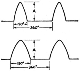
Fig. 2. Shape of plate-current pulses in normal power-amplifier operation with 120 degree excitation (above) and 180 degree excitation (below).
The smaller the angle the higher the efficiency, provided other operating conditions are adjusted to match. The plate-current waveshapes for the 120-degree and 180-degree cases are shown in Fig. 2. Although these drawings represent the way in which the d.c. plate current varies, with the base line in each case representing zero current, on the equivalent-generator basis we consider them as representing complete a.c. waves, ignoring the fact that there is d.c. present. In other words, the equivalent generator is putting a distorted a.c. wave into the load.
The relative second-harmonic content of the two waveshapes shown will give us some idea of the improvement to be expected by reducing excitation, since the 120-degree case represents high-efficiency Class C operation and the 180-degree case Class B. In terms of the peak-to-peak amplitude, A, of the wave, the two cases compare as follows:(1)| 120 degrees | 180 degrees | |
|---|---|---|
| Amplitude of fundamental component | 0.40 | 0.50 |
| Amplitude of second-barmonic component | 0.28 | 0.21 |
| Ratio of second harmonic to fundamental | 0.70 | 0.42 |
For a tube driven to the same peak plate current in either case, the second-harmonic content will be reduced by a factor of 0.21/0.28, or 0.75, by using an operating angle of 180 degrees instead of 120 degrees. This does not represent much improvement, although it should be observed that since the fundamental component is larger with 180-degree excitation, a somewhat better picture is obtained on the basis of the individual harmonic/ fundamental ratios.
Comparison on the basis of the same peak plate current probably is not entirely legitimate, because with 180-degree excitation the average plate current (the value read by the plate milli-ammeter) increases 46 per cent over the 120-degree case. The probability is, therefore, that the tube or tubes would be overloaded. If the comparison is made on the basis of the same average plate current, the second harmonic with 180-degree excitation will have only 53 per cent of the amplitude of the same harmonic with 120-degree excitation. However, the fundamental component also is smaller - slightly under 70 per cent of the 120-degree figure. Perhaps the fairest basis of comparison - although it may not represent what can be done with a given tube or tubes in view of plate-dissipation limitations - is the same fundamental component in both cases; on this basis, the second harmonic with 180-degree excitation will have 62 per cent of the value it has with an operating angle of 120 degrees.
Whatever the means of comparison, the reduction in second harmonic appears to be only of the order of 4 to 6 dB, or about one point in the S scale. The normal fading in sky-wave transmission would make it hard to tell that any improvement had been made. Reducing excitation does not appear to be the solution to the harmonic problem - not unless the reduction is so drastic that Class A operation is approached. Few hams would be willing to sacrifice tube capacity to that extent. Besides which, Class C operation is a necessity if the amplifier is to be plate-modulated.
Tank Q and L/C ratio
If the tube worked into a resistance load such as the equivalent circuit shown in Fig. 1, the picture would be pretty discouraging because the second-harmonic component of the plate current is only 3 db. below the fundamental component. However, the actual load is a tuned circuit that is resistive only at resonance. It can be represented as in Fig. 3, where the resistance R is understood to be the "coupled-in" resistance; in other words, the parallel-resistance equivalent of the power-absorbing capabilities of the actual load (which may be the antenna system) at resonance. As is usual in such cases, it is assumed that the parallel impedance of the tank circuit alone is so high that practically all of the power delivered by the generator is absorbed in R - that is, the losses in the coil and condenser by themselves are negligible. Since R is, for the moment, assumed to absorb power only at the fundamental frequency, it does not exist at the harmonic frequencies. For the harmonics we have only the reactances of the coil L and condenser C in parallel.
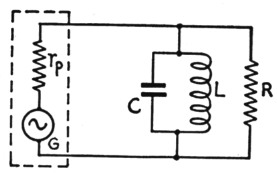
Fig. 3. A loaded tank circuit can be considered to be equivalent to a high-Q resonant circuit in parallel with a load resistance, R, that absorbs the power output of the generator.
Now since the amplitude of the second-harmonic component in the alternatin plate current ("line" current) is fixed by the operating conditions that determine the shape of the plate-current pulse, it is clear that no variations in tankcircuit Q or L/C ratio can affect the second-harmonic amplitude so long as the same plate-current waveshape is maintained. Then since the harmonic component must flow through the tank circuit and will have the same amplitude regardless of Q, it is obvious that there will be no "suppression" of harmonics by high-Q or high-C tank circuits.
At the fundamental frequency the reactances of the tank coil and condenser are equal. At the second harmonic the condenser reactance is halved and the coil reactance is doubled. Because of this, the second-harmonic current in the condenser will be four times as large as the second-harmonic current in the coil. However, the two currents are 180 degrees out of phase, which causes the condenser current to have a value equal to 4/3 the second-harmonic line current and the coil current to be 1/3 the line current. With 120-degree excitation, where the second-harmonic component of line current is 0.7 times the fundamental component, the second-harmonic current in the coil is consequently equal to l3 × 0.7, or approximately ¼ of the fundamental component of line current. This ratio will hold regardless of L/C ratio, since the ratio of the coil and condenser reactances always must be constant.
The benefits of high-Q tank circuits lie not in suppression of harmonics but in the fact that they build up the fundamental component of line current. If the operating Q is 10, for example, the fundamental current in either the coil or condenser will be 10 times the fundamental component of line current. This means that the ratio of fundamental to second-harmonic current in the tank coil will be 40, since the second-harmonic current is equal to % the fundamental current in the line. The ratio increases in direct proportion to the Q. In circuits using inductive coupling to the load the current in the coil is the important thing because this current provides the means for magnetic coupling.
Fig. 4 is a general type of circuit having inductive coupling to a load resistance, R, which is assumed to have the same resistance at all frequencies. With the available power output and load resistance fixed at definite values, the desired power will be obtained at a definite value of voltage across R. Now the voltage induced in L2 is proportional to the primary current, the frequency, and the coupling between L1 and L2; consequently, the higher the primary current the looser the coupling may be to obtain the necessary voltage across R. Hence high Q, by raising the fundamental component of primary current, permits looser coupling between the two coils for the same power delivered to the load. But since the value of second-harmonic current is not affected by the tank-circuit Q, the second-harmonic voltage induced in L2 is reduced by the looser coupling. Looser coupling is, in fact, the whole secret, and high Q is beneficial simply because it makes loose coupling practicable.
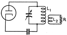
Fig. 4. A simple type of output circuit. In practice, R usually is replaced by _ a nonresonant transmission line that simulates a pure resistance at the funda. mental frequency.
Even so, it does not pay to go to extremes. Doubling the Q and readjusting the coupling would reduce the second-harmonic voltage induced in the secondary circuit by a factor of 2, which is about an "S" point. But doubling the C/L ratio cannot be done many times without running into unworkable values of inductance and capacitance, which in practice would defeat the purpose because the tank current would become so high that tank losses no longer would be negligible - meaning that the actual Q would not increase with the C/L ratio. The optimum appears to be a Q between 10 and 20.
Fig. 4 probably represents the worst possible case. With a 40-to-1 ratio of fundamental to second-harmonic current in the tank coil, the harmonic in the load would be 26 dB below the fundamental, while raising the Q to 20 would drop the harmonic down to 32 dB. However, there are few, if any, practical applications where the load resistance would be the same at all frequencies. The circuit of Fig. 4 is equivalent to a tank circuit coupled to a flat line at the fundamental frequency, but at the second harmonic the load may be anything from a short-circuit to an open-circuit, depending upon the electrical length of the line and the characteristics of the antenna in which it is terminated. Where the line is matched to the antenna the termination is more likely than not to represent a short-circuit for the second harmonic, with the result that the radiated harmonics power is negligible compared to the fundamental.
However, it is an easy matter to improve the situation to the point where there is a large factor of safety by using two tank circuits, as in the common form of link-coupled antenna tuner shown in Fig. 5. Because of the resonant rise in voltage in the tuned secondary circuit, L2C2, the voltage developed across the load will be greater than the voltage applied to the load in Fig. 4 by a factor equal to the Q of the secondary circuit. Thus if the secondary circuit Q is 10, the voltage will be ten times as great as with a non-resonant coupling coil. This means that, for the same voltage across the load, the coupling between L1L2 need be only one-tenth as great for the same power transfer as between L1L2 in Fig. 4. (The link between the two circuits, incidentally, is simply a convenient means for providing mutual inductance between the coils.) Consequently, the second-harmonic voltage induced in L2 will be reduced by a factor of 5, as compared with the conditions existing in Fig. 4. This alone would give an additional improvement in the fupdamental/harmonic ratio of 14 dB, but the actual situation is more favorable because again the load is not likely to have the right value for maximum power transfer at both the fundamental and harmonic. On the whole, it is reasonable to expect that the fundamental/harmonic ratio through a system such as is shown in Fig. 5 should be of the order of 50 dB in practice. Even at the maximum power authorized for amateur stations the second-harmonic power in the antenna should be but a small fraction of a watt.
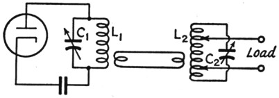
Fig. 5. The link-coupled antenna tuner provides additional selectivity to help in the discrimination against harmonics.
Nevertheless, the fact is that stations using just these coupling systems, particularly the type in Fig. 4, do get tickets for harmonic radiation. Part of the reason is that those who get cited have harmonics falling outside an amateur band where they stand out like the well-known sore thumb even though the harmonic power radiated undoubtedly is quite small. But in many cases the ratio between harmonic and fundamental is not anything like the ratios arrived at by the reasoning above. If the harmonic is not getting into the antenna through magnetic coupling there is only one thing left - capacity coupling.
Coupling through stray capacity
As an example, consider the arrangement shown in Fig. 6-A. Here a half-wave antenna is center-fed by a transmission line which - although no attempt has been made to show it pictorially - is assumed to be matched to the impedance at the center of the antenna. The line gets power from the transmitter tank through the usual small coupling coil such as a variable link. The possibility that any appreciable second-harmonic power could get into the antenna through magnetic coupling and ordinary transmission-line operation is rather remote, as we have seen. But there is capacitance between the tank and coupling coils, as indicated in Fig. 6-B, and r.f. current can flow .through this capacitance from the tank to the line. There is no particular reason why this current should know that it is supposed to behave itself on a transmission line; in fact, there is every reason why it should not. With magnetic coupling the voltages at the ends of the coil are opposite in phase with respect to the two sides of the line, hence the currents flow in opposite directions in the two wires. But the voltage across the stray capacitance is in practically the same phase all across the secondary coil, with the result that current flows in the same direction in both sides of the line. The line, in other words, is simply two conductors in parallel for the harmonic, and the currents arrive at the center of the antenna in phase. Since each side of the antenna is a half wavelength long at the second harmonic, the whole system simply acts as a full-wave antenna fed at the center by a single-wire transmission line; the only difference is the purely mechanical one that the line and antenna sections are separate wires. Of course, the "line" radiates, too, since the usual cancellation does not exist. If the line happens to be near a multiple of a half-wavelength long at the harmonic, conditions are almost ideal for absorbing and radiating a great deal of the harmonic power in the tank, because under such conditions a very small coupling capacitance will suffice for maximum power transfer.
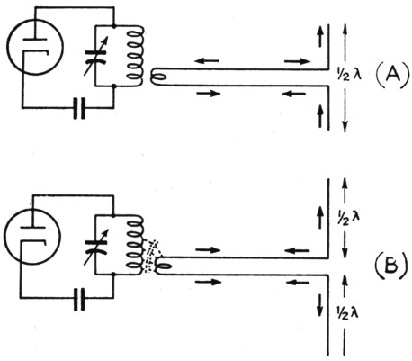
Fig. 6. Current flow on the antenna and transmission line at the fundamental frequency (A) with magnetic coupling to the line, and current flow (B) through stray capacitance between the tank and coupling coils. In the latter case there is no essential difference between the line and a single conductor, since the two wires act in parallel.
Similar conditions can exist in almost every type of antenna-feeder system just so long as there is stray capacitance between coupling coils. Installing a separate antenna tuner such as is suggested in Fig. 5 will improve things to the extent that it cuts down the stray capacitance because there are two coupling points instead of one. In itself this is quite advantageous, particularly with the loose coupling that reasonably high-Q circuits make possible, because loose coupling between coils reduces the stray capacitance. Also, since in transmitters high Q is achieved by reducing the L/C ratio, the harmonic voltage developed across the tank coil also is reduced, the amplitude of the harmonic current being independent of the L/C ratio. But there is nevertheless still a possibility that a great deal more harmonic will get through than should.
The real answer, obviously, is to eliminate the stray capacitance. A time-honored device is the Faraday shield - and there is nothing better. But such shields are not only rather difficult to make but cumbersome to instill and use, particularly with plug-in coils. There is a simple dodge that works almost as well as the shield, doing the job by reducing the effect of the capacitance, although not eliminating the capacitance itself.
Of the total harmonic voltage coupled from the tank, the greater proportion appears between the coupling coil and ground (that is, the cathode return on the amplifier), and only a small part appears across the stray capacitance when power is being transferred. But if the coupling coil is brought to ground potential there will be no harmonic voltage between the coil and ground and all of it will appear across the stray capacitance. In effect, this short-circuits the harmonic at the point where it is coupled to the antenna system. It is impossible, of course, to connect every part of the coupling coil to ground, but the equivalent effect can very nearly be realized by making a single connection to any part of the coil. To maintain the symmetry of the system at the fundamental frequency, probably the most desirable point to ground is the center of the coil, as in Fig. 7-A. Combined with coupling to the "cold" point on the tank, this should pretty effectively eliminate coupling through stray capacitance. The ground connection should be to the transmitter chassis and should be short; if the lead has appreciable reactance at the harmonic frequency it will not be a short-circuit at all.
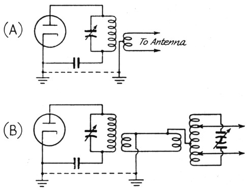
Fig. 7. Grounding the coupling coil to reduce the effect of stray capacitance by short-circuiting the harmonic voltage in the link and antenna circuits.
It would be hard to overemphasize the importance of coupling through stray capacitance as a factor in harmonic radiation. We recently had occasion to look into two cases of excessive harmonics, and in both instances eliminating the effects of stray capacitance reduced the harmonic to the point where it was not appreciably stronger with the antenna on than it was with the antenna system completely disconnected. The remaining radiation, in other words, was practically entirely from the final tank circuit itself, a condition that can be cured only by proper shielding. The two transmitters concerned were widely different, one being ti low-power outfit with a single-ended final tank circuit and the other a moderately high-power push-pull amplifier. In the latter case the second-harmonic signal was of good "local" strength at a distance of about two miles; grounding the antenna coupling coil reduced it to the point where it was not more than 50 per cent readable, with no difference in strength whether the antenna was on or off.
When a link-coupled antenna tuner is used between the final tank and the feeders, it is advisable also to ground the center of the coil in the antenna tuner, assuming that a balanced feeder system is used, as indicated in Fig. 7-B. A short lead is called for here also. Note that the link coil at the amplifier tank also is grounded; this is the really important ground. As suggested in the diagram, the side of the link farthest from the cold end of the tank should be connected to ground because that is the "hottest" end of the link (especially when the link is wound over the tank) and therefore the place where the stray capacitance voltage needs to be short-circuited.
Incidentally, it should be rather obvious that the way really to ask for harmonic trouble is to use direct coupling between the tank and feeders. Low-pass filters such as the pi-section coupler don't have a chance to work when the harmonic currents flow through both sides in the same direction. And direct coupling is practically synonymous with maximum coupling for harmonics as compared to the coupling through stray capacitance.
Push-pull
The old saw that "even harmonics cancel out in push-pull amplifiers" is one of those dangerous half-truths that generate a false sense of security. It is true in a push-pull audio amplifier. In a push-pull class-c r.f. amplifier the cancellation may or may not be effective.
Let's take the case of two tubes in push-pull from the equivalent-generator standpoint. For a 120-degree plate-current pulse the amplitudes and phases of the fundamental and second-harmonic components are approximately as shown in Fig. 8. This picture is for one tube only. Since the grids of the two tubes are excited 180 degrees out of phase there is a difference of one-half cycle (at the fundamental frequency) in the operating conditions of the two tubes. In other words, if one tube is operating at Point A in Fig. 8, then the other tube is simultaneously operating at Point B. The fundamental components in the output are 180 degrees out of phase, which means that the two tubes are supplying current to the tank circuit in series. However, the phase difference in the second-harmonic component is 360 degrees, which means that the second-harmonic currents are in phase at the ends of the tank circuit. These instantaneous conditions are perhaps made a little clearer by Fig. 9, which shows the instantaneous polarities at the grid and plate corresponding to A and B in Fig. 8. The resulting current flow is shown by the solid arrows for the fundamental component and by dotted arrows for the second-harmonic component. Since the latter currents are flowing in opposite directions through the two halves of the tank coil their magnetic fields tend to cancel out. However, true cancellation does not occur unless there is 100-per-cent coupling between the two halves of the coil. No r.f. coil has anything like that coupling, with the result that although the fields may practically cancel near the center of the coil there is little if any cancellation near the ends. Nevertheless, with a symmetrical circuit and a coupling coil inserted at the center so that it has equal coupling to the two halves of the coil, very little second-harmonic voltage will be induced in the output circuit by magnetic means.
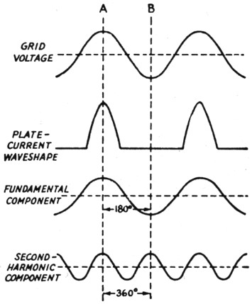
Fig. 8. In a push-pull amplifier the grids of the two tubes are excited 180 degrees out of phase, so that when one tube is at Point A in the cycle the other is simultaneously working at Point B. The fundamental components of plate current are out of phase but the second-harmonic components are in phase.
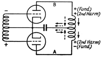
Fig. 9. Instantaneous polarity of fundamental and harmonic voltages at the ends of a push-pull tank coil and directions of current flow at the same instant. Dotted arrows show direction of second-harmonic component, solid arrows direction of fundamental component.
However, Fig. 9 is not a practicable amplifier circuit for radio frequencies. Probably the most common type of tank circuit is that shown in Fig. 10-A, using a split-stator condenser with the rotor grounded. The other type, less commonly used nowadays, has the center of the coil grounded and the condenser rotor floating. From the harmonic standpoint there is considerable difference between the two. In Fig. 10-A the harmonic currents cannot flow from each tube through the halves of the coupling coil to ground because there is an r.f. choke in the return lead. Consequently, practically the entire second-harmonic component is carried to ground through the two condenser sections. However, the harmonic voltages developed across the condenser-section reactances appear at the ends of the tank coil, and since no current flows in the coil the same voltages (they are identical in amplitude and phase) appear at every part of the coil, including the center-tap. Insofar as second-harmonic coupling through stray capacitance is concerned, it makes no difference whether the coupling coil is at the center of the tank coil or not. The center of the coil is just as hot as the ends at the second harmonic. But since there is no second-harmonic current in the coil there is no possibility of magnetic coupling to the output circuit. With a good Faraday screen between the two coils this circuit will have practically zero even-harmonic output.
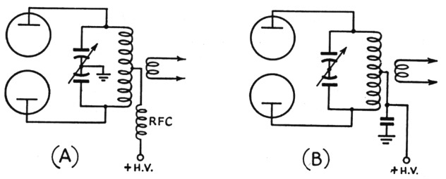
Fig. 10. Two methods of grounding the center point of a push-pull tank. The differences in respect to harmonic operation are discussed in the text.
In Fig. 10-B, the second-harmonic current components flow through the two halves of the coil just as in Fig. 9. In this case the voltage at the center of the coil is zero, so coupling through stray capacitance to the coupling coil at this point is minimized - but it should never be assumed that it is negligible. A coupling coil concentric with and close to the tank coil can have enough capacitance to the tank to transfer considerable harmonic energy to the antenna. Grounding the coupling coil or the installation of a screen is just as advisable as in the case of Fig. 10-A. In this circuit magnetic coupling of the even harmonics is eliminated to the extent that the coil and circuit as a whole are balanced. With reasonable care it should be quite small.
With care taken to eliminate stray capacitance, the circuit at A has a slight edge on B. Without such care, A is far more likely to put out a strong second harmonic than B, but both can be troublesome.
Other circuits
The push-pull discussion should make it plain that because a circuit behaves one way at the fundamental frequency, there is no guarantee that it will do the same at harmonics. In a single-ended amplifier with plate neutralization using a grounded split-stator condenser, for instance, there is a voltage node at the center of the tank coil at the fundamental frequency. But a little study of the circuit will show that there is no node at that point for the second harmonic; there is a node, but it appears near the end of the tank coil farthest from the tube. On the other hand, if the center of the coil rather than the rotor of the condenser is grounded, there is a node at the coil center - but the second-harmouic voltage across each half of the coil is almost four times as large as the voltage across the whole coil in the grounded-condenser circuit. However, in this case the harmonic currents in the two halves flow in opposite directions through the coil, just as in the push-pull case, so magnetic coupling is decreased. There is no such thing as complete cancellation because the two currents in the two halves of the coil are not exactly in phase, in addition to the fact that the coupling between the coil sections is rather loose.
Other harmonics
Although not negligible, harmonics higher than the second are less likely to be bad offenders. The amplitude of the third harmonic with 120-degree excitation, for example, is only 20 per cent of the fundamental-component amplitude, and as we continue up the harmonic scale the amplitudes decrease rapidly. Also, the tank reactances decrease in proportion, so the harmonic voltages appearing across the tank coil drop off with considerably greater rapidity than the harmonic components themselves. Both things are favorable to reduction of harmonic transfer either magnetically or through stray capacitance.
However, it would be dangerous to neglect them. To offset the assets of smaller current and lower voltage, there is a greater likelihood of unsuspected resonances in the antenna-feeder system that may result in efficient radiation of the small amount of power available. This is one reason why the ground leads to coupling coils and links should be as short as possible. In addition, push-pull amplifiers may get into difficulties with some antenna systems because the third and other odd harmonics flow through the tank circuit in the same way as the fundamental component. This is favorable to magnetic coupling - and unfortunately most antenna systems in which the impedances are matched at the fundamental frequency also are fairly closely matched at odd-harmonic frequencies. The additional selectivity provided by a tuned antenna coupler of reasonably high Q is the best solution.
To sum up:
- Don't take it for granted that you have no appreciable harmonic radiation; the chances are that you have. Radiation from a tank coil alone can bring in a ticket when propagation conditions are right.
- Don't worry about excessive g d drive. A Class C amplifier can't be operate without strong harmonics, and within the Clas C range there isn't much that can be done to reduce them.
- Use a tank Q of 10 or more, but don't carry the reduction of L/C ratio to the point where the loaded tank starts to run hot.
- Use an antenna tuner having at least the same Q as the final tank and tune the whole system "on the nose" - in other words, with the loosest coupling that transfers the power to the antenna.
- Use a Faraday screen between the final tank and the coupling coil, if possible. If it's out of the question for constructional reasons, ground the coupling coil to the final chassis by a short lead, and ground the center of the antenna-tuner coil to the same side of the link. See Fig. 7.
- After you've done these things (they should be done in any case) get a nearby ham friend to listen for your harmonics, up to the limit of his receiver's frequency range. In the case of each one heard, check by removing the feeders from the vicinity of the transmitter to see if the radiation is from the transmitter itself. If the transmitter is radiating a strong harmonic some shielding is in order.
- Before you decide that all this is too much trouble, remember that it's your record in the FCC files that gets the black mark when the pink QSL starts on its way.
Notes
- Formulas for calculating these values are given in Reference Data for Radio Engineers, published by Federal Telephone & Radio Corp., 67 Broad St., N.Y.C.
George Grammer, W1DF.