Home - Techniek - Electronica - Radiotechniek - Radio amateur bladen - QST - A new phase-modulation circuit for narrow-band F.M. transmission
Modulator-exciter unit for either crystal or VFO control.
Here's a new f.m. modulator circuit, one that gives adequate frequency deviation for amateur narrow-band f.m. from a crystal-controlled source, while requiring only a relatively small amount of frequency multiplication. It's the circuit used in a commercially-built f.m. exciter that has helped solve the BCI problems of the city-dwelling 10- meter 'phone man.
The advantages of f.m. ooer a.m. have been listed so many times in the literature in the past decade that they should be a familiar story to most amateurs. However, in view of the rapidly-increasing interest in the narrow-band variety of f.m. at the present time it is not out of place to review them once more. Accent is usually placed on the noise-reducing qualities of f.m. reception, and it is true that, for the same bandwidth as is occupied by an a.m. transmission, an improvement in signal-to-noise ratio over a.m. is possible on weak signals; that is, for equal readability, a weaker carrier will suffice with narrow-band f.m. and a good f.m. receiver than with a.m. and a correspondingly-good a.m. receiver.
Now many of us have good narrow-band f.m. receivers. But inasmuch as it is possible to receive narrow-band f.m. transmissions on the ordinary communications receiver, at little if any disadvantage as compared to a.m. reception on the same receiver, it is not necessary for the receiver problem to be solved before the transmitter advantages can be realized. These are impressive: (1) F.m. costs less initially than a.m., since the speech equipment operates at no more than receiver power level and no expensive high-power audio or power-supply equipment is needed for the modulating system. (2) Power consumption is reduced - i.e., the over-all efficiency is higher - because the audio power required for f.m. is negligible. Furthermore, the same modulator is equally effective with a transmitter of any power-output level. (3) More carrier power output can be obtained from a given tube or tubes in the final r.f. stage because the tubes can be operated at c.w.-telegraph rather than 'phone ratings. (4) Excitation requirements for the final stage are less severe, since there are no amplitude peaks to care for and the quality of the modulation is unaffected by the amount of drive available for the output stage. (5) Tank and auxiliary components in the final stage need only be adequate for c.w. operation, since there are no high-amplitude modulation peaks with f.m.
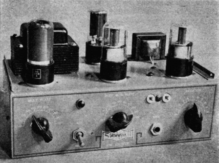
The chassis layout of the fm exciter unit s simple. Power-supply components and rectifier are along the rear edge. Along the front, from left to right, are the 6V6GT doubler, 6SL7GT oscillator-modulator, and 6SL7GT speech amplifier. Controls along the front are the doubler tuning, modulator tuning, and audio gain. The crystal socket and microphone jack are between the two latter controls.
There are two additional advantages to f.m. transmission that do not exactly fit into the transmitter list. Both are of definite benefit to the "other fellow," and one is invaluable to the operator of the transmitter. The first is the fact that excessive frequency swing with f.m., although creating additional sidebands outside the channel normally required, does not have the same effect as overmodulation with an a.m. transmitter. In the overmodulated a.m. case, the sudden carrier cut-off when the down-peaks exceed 100 per cent is similar to a key click in c.w. transmission, and overmodulation splatter can and does cause bad interference of an especially irritating nature over a frequency spectrum all out of proportion to the bandwidth actually required for a.m. transmission. Like key clicks, splatter causes plenty of trouble with nearby broadcast receivers as well. The same percentage of excess deviation in an f.m. transmitter simply causes the channel occupied to expand in proportion to the deviation, but does not produce the spurious frequencies associated with a.m. overmodulation.
The second advantage has been mentioned a number of times in QST recently: F.m. practically eliminates broadcast interference of the type associated with r.f. pick-up in the audio systems of b.c. receivers - a type of pick-up that is only too common, especially in the h.f. and v.h.f. region, and probably accounts for the major part of BCL troubles on all frequencies. As for the tunable types of BCI, narrow-band f.m. is certainly no worse than a.m.
Producing narrow-band F.M.
Methods for the production of frequency-modulated signals can be divided into two general groups, those in which the frequency of a self-controlled oscillator is varied by some such device as the reactance modulator, and those in which the frequency-stabilized output of a crystal-controlled oscillator is shifted in phase at an audio-frequency rate. Since a change in phase is equivalent to an instantaneous change in frequency, phase modulation produces effects that are identical with frequency modulation except that with phase modulation the frequency deviation is proportional to the rate at which the phase is shifted - in other words, is proportional to the modulating frequency. To produce true frequency modulation from phase modulation, it is only necessary to shape the frequency-response curve of the al system so that the output amplitude is inversely proportional to frequency.
The advantage of phase modulation over direct frequency modulation lies in the fact that the carrier frequency is as stable as the crystal oscillator that generates it. The self-controlled oscillator, even when well designed and properly built, is ordinarily more sensitive to voltage fluctuations, temperature changes, mechanical vibration, and so on than the simplest crystal oscillator. These effects are magnified when such an oscillator is modulated by a reactance tube not only because the modulator tube must be connected across the tank circuit and thereby adds new sources of instability, but also because the oscillator tank circuit cannot be made very high-C without restricting the frequency deviation obtainable. To provide a high order of carrier stability, commercial f.m. transmitters using reactance-tube modulators employ auxiliary circuits that provide a means for comparing the carrier frequency with that of a stable crystal-controlled oscillator, and for bringing the carrier back to the proper frequency whenever it has a tendency to wander. Since such circuits are practically as complicated as an f.m. receiver, they are not too attractive for amateur transmitters.
A number of types of phase modulators have been developed in the past several years for various different services, but none has been capable of producing a frequency swing comparable to that obtainable from a reactance modulator in conjunction with a self-controlled oscillator. The result has been that a large amount of frequency multiplication has been required for a deviation of even a few kilocycles. In the circuit to be described, the frequency deviation is comparable to that obtainable from the reactance-type system when the latter is used with a reasonably high-C self-controlled oscillator.
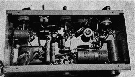
Power-supply equipment is along the lower edge in this bottom view. The audio and r.f. components occupy the upper section, grouped near the tubes with which they are associated.
The operation of the new circuit, shown in Fig. 1, can be visualized best in terms of a simpler circuit used in some f.m. transmitting equipment built for military use.(1) A triode tube is used as a resistance-coupled r.f. amplifier and, since there is no shielding between the grid and plate, the r.f. grid voltage will cause an r.f. current to flow through the grid-plate capacitance and the load circuit. This is in addition to the normal r.f. plate current caused by ordinary amplifier action in the tube. The voltage components developed across the plate resistor, R4, by these two currents are not in phase, since the voltage drop caused by current flow through Cgp is more or less in phase with the grid voltage while the voltage drop caused by amplifier action is essentially 180 degrees out of phase with the grid voltage. The exact phase relationship depends on the impedance of the load circuit and is affected by the plate-to-cathode capacitance, Cpc, of the tube. The vector diagram in Fig. 1 is reasonably typical; E1, the component of plate voltage caused by Cgp leads the applied grid voltage by a small angle, and E2, the component resulting from amplification, is slightly less than 180 degrees out of phase with the grid voltage. E1 and E2 combine to give the resultant r.f. plate voltage, Ep.
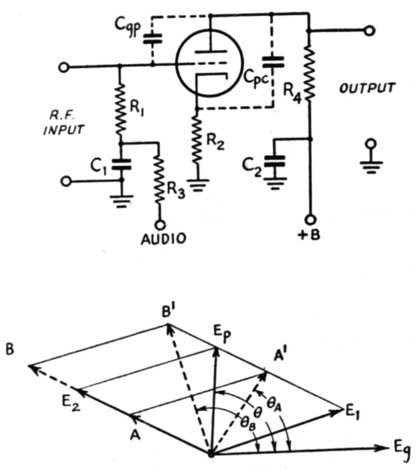
Fig. 1. A simple form of phase modulator, with vector diagram showing how the phase of the r.f. output voltage varies when the amplitude of component Ea is varied at an audio-frequency rate. E2 is the amplified grid voltage and Et is the component that reaches the output circuit through the grid-plate capacitance of the tube.
When an audio-frequency voltage is applied to the grid of the tube the mutual conductance - and consequently the amplification - is varied at an audio rate. The variation in amplification causes the voltage E2 to vary likewise; with a steady audio signal it might swing between the limits A and B in Fig. 1. Since E2 combines with the unvarying component E1 vectorially, the resultant voltage, Ep, is varied in phase with respect to the grid voltage between the limits A' and B'. Larger or smaller audio signals will cause correspondingly larger or smaller shifts in the phase of Ep with respect to Ea.
In order for the phase shift to be linear with respect to the audio swing, the two voltage components E1, and E2, should be of approximately the same magnitude. E2 would ordinarily be much larger than E1 because it represents the amplified output of the tube. To reduce the amplification, negative feed-back is introduced by means of the cathode resistor, R2. C1 is an r.f. by-pass in the grid circuit, and in conjunction with R3 also provides the necessary audio compensation to convert the phase modulation into frequency modulation. It will be observed that the output is amplitude-modulated as well as phase-modulated, as indicated by the change in length of the vector Ep when swinging between A' and B'. Amplitude modulation is not serious when E2 is about equal to E1, and is easily washed off in the following frequency-multiplier stages.
So much for the basic idea. The new circuit(2) is shown in fundamental form in Fig. 2. Instead of a simple resistor in the plate circuit there is a tuned tank, L1C3. L2 is a continuation of L1, the turns ratio between L1 and L2 being approximately 2.4 to 1. L2 with C4 resembles the familiar neutralizing circuit used with a straight-through triode amplifier, but its purpose in this case is not to neutralize the amplifier but to provide an adjustment for the phase and amplitude of the voltage acting between the grid and the plate. Similarly, C3 offers a means for varying the magnitude and phase angle of the impedance in the plate circuit. By these two means alone it is possible to increase considerably the phase shift obtainable, and thereby increase the frequency deviation. However, still greater deviation is secured by inserting a powdered-iron slug in the coil, the characteristics of the iron being such that an additional phase shift is introduced when the d.c. plate current of the tube is varied by the audio-frequency signal. In total, the frequency deviation obtainable with this circuit is nearly 1.5 kc. at a crystal frequency of 4 megacycles, as compared to about 250 cycles for the circuit of Fig. 1.
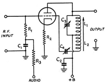
Fig. 2. The modulator circuit discussed in the text. A tuned plate circuit and feedback connection (L2C4) provides means for increasing the phase swing. Further improvement is secured by using an iron-core coil.
A practical exciter circuit
A complete circuit for a modulator-exciter using this method of phase modulation is shown in Fig. 3. Intended for narrow-band f.m. in the 29-29.7-Mc. band, it uses crystals lying in the frequency range 3625-3712 kc. and, after the necessary multiplication of 8 times to reach the 29-Mc. region, will easily produce a frequency swing of 10 to 12 kc. at 29 Mc.(3) As indicated in the circuit diagram it uses one section of a dual-triode 6SL7GT as a Pierce-type crystal oscillator and the other triode section as the phase modulator. The crystal and modulator operate on 80 meters, and the output of the modulator is fed to a 6V6GT doubler so that the final output of the unit is on 7 Mc. Such amplitude modulation as is introduced by the modulator is eliminated in the doubler stage. With a normally-active crystal, the power output is approximately 3.5 watts - sufficient as a substitute for the crystal oscillator in many transmitters, or for driving a following frequency multiplier.
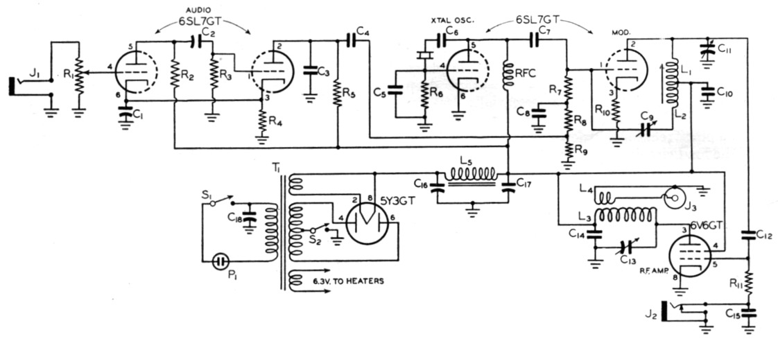
Fig. 3. Circuit diagram of the f.m. exciter unit.
| C1 | 25 µF 25 volt electrolytic. |
| C2,C4 | 0.01 µF paper. |
| C3 | 400 pF mica. |
| C5 | 50 pF mica. |
| C6,C8,C10,C14,C15 | 0.005 µF mica. |
| C7,C12 | 250 pF mica. |
| C9 | 2 pF variable. |
| C11,C13 | 75 pF variable. |
| C16,C17 | 8 µF electrolytic, 450 volts. |
| C18 | 0.1 µF paper. |
| R1 | 0.5 MΩ volume control. |
| R2,R3,R5,R9 | 250 kΩ,½ watt. |
| R4 | 1000 Ω, ½ watt. |
| R6 | 30 kΩ, ½ watt. |
| R7 | 50 kΩ, ½ watt. |
| R8,R10 | 25 kΩ, ½ watt |
| R11 | 100 kΩ, ½ watt |
| L1 | 36 t. No. 36 enam. ½ inch diam. form. Powdered-iron core. |
| L2 | 15 t. No. 36 enam. spaced ¼ inch from L1. ½ inch diam. form. Powdered-iron core. |
| L3 | 37 t. No. 20 enam., close spaced, ¾-inch diam. |
| L4 | 2 t. of hook-up wire on cold end of L3. |
| L5 | 20 HW, 70 mA |
| J1 | Open-circuit jack. |
| J2 | Closed-circuit jack. |
| J3 | R.f. output receptacle. |
| P1 | 115-volt plug. |
| RFC | 10 mH r.f. choke. |
| S1 | S.p.s.t. switch (mounted on R1). |
| S2 | S.p.s.t. toggle. |
| T1 | Power transformer, 250 to 300 volts d.c. at 70 mA, with 6.3- and 5-volt windings. |
The proper r.f. and a.f. voltages are secured in the modulator circuit by means of the degenerative cathode resistor, R10, and the grid voltage divider, R7R8R9. R8 and C8 form a correcting network having an a.f. attenuation of 6 dB per octave, above 2000 cycles, to convert the phase modulation to frequency modulation.
A second 6SL7GT is used as a two-stage resistance-coupled audio amplifier for driving the modulator. The input circuit of the amplifier is suited to high-impedance microphones of either the crystal or dynamic variety. A level of -48 to -55 dB - easily supplied by a communications-type microphone - at the input jack is ample for full modulation. The gain control, R1, sets the amount of frequency swing for a given voice level, and is appropriately named the "deviation control."
The construction- of the unit is not difficult, as shown by the photographs of the Sonar Model KE-10 F.M. Exciter in which this circuit is used. The parts layout follows the circuit diagram approximately, with the speech amplifier at one end of the chassis, the oscillator and modulator in the center, and the output tube at the other end. Reasonable care should be used to keep the components associated with a particular tube grouped so that leads will be fairly short.
The method of coupling the unit to the transmitter will depend primarily on the transmitter itself, and any of the methods that are successful with a VFO having 7-Mc. output may be used with this exciter. In cases where there is a 7-Mc. crystal oscillator or doubler operating at a power level of three watts or so, the simplest scheme is to wind a coil of a few turns around the 7-Mc. tank, connect it through a length of twisted pair, coax or Twin-Lead to the output link in the exciter, and remove the tube associated with the 7-Mc. tank in the transmitter from its socket.
To set the unit in operation, plug in a crystal of appropriate frequency, connect a 0-1 milliammeter in the doubler grid return through J2, and tune Cu for maximum grid current. The current should be at least 0.3 ma. and probably will run considerably higher. Then tune the doubler tank circuit to resonance by varying C13 until a neon bulb brought near the hot end of Ls shows maximum glow. The various stages in the transmitter with which the exciter is used should be tuned in the normal way.
Next, listen to the 29-Mc. signal in a receiver, adjusting the gain for a signal level about the same as that of incoming signals. It may be desirable to cut off the final amplifier in the transmitter to avoid overloading - and it is usually possible, in fact, to get sufficient signal from the 29-Mc. harmonic from the exciter alone, the rest of the transmitter being off completely. Set R1 at about half scale and have someone talk into the microphone in a normal tone. While listening, vary Cu to find the setting that gives maximum modulation. The audio level will come up tremendously with slight detuning from exact resonance, and the 6V6GT grid current usually will drop off by about 0.2 ma. at the correct setting of Cu. That is all there is to getting on the air with narrow-band f.m., but it is advisable to check the sidebands, using the receiver crystal filter in the sharp position, to see that they do not extend beyond the limits of the channel occupied by an a.m. station. The deviation or gain-control setting that gives full modulation without excessive channel width is the best one to use, since any wider swing will not be accepted by the i.f. channel in the ordinary communications receiver.
If desired, a VFO may be used instead of the crystal oscillator. The output of the VFO (which should incorporate the usual buffers for good carrier stability) can be fed into the crystal socket prong that connects to the grid of the first section of the 6SL7GT, the other side of the line from the VFO being connected to ground. The VFO output should be in the 3.5-Mc. band, since it replaces a 3.5-Mc. crystal, and should have sufficient output to give a minimum of 0.3 mA grid current in the 6V6GT.
For receiving narrow-band f.m., any a.m receiver having a 4- to 6-kc. pass-band can be used with good results simply by detuning so that the carrier is placed on the slope of the i.f. selectivity curve. However, this is far from the ideal method of f.m. reception because it gives none of the discrimination against amplitude noise that is characteristic of a true f.m. receiver. But there is no reason why a couple of limiters and a discriminator having a bandwidth of approximately 6 kc. cannot be hooked to a communications receiver and thereby make the full benefits of improved signal-to-noise ratio with f.m. possible.(4)
Notes
- This circuit was developed by the Link Radio Corporation and used in a number of military and commercial applications.
- Patent applied for.
- It can obviously also be used on the 11-meter band with proper crystal selection, and the deviation is large enough for successful wider-band operation at 50 and 144 Mc. The deviation at 14 Mc. is sufficient for that frequency in the event that use of narrow-band frequency modulation should be authorized there.
- For constructional details of such a unit, see Grammer, "Some thoughts on amateur F.M. reception," QST March. 1941.
Jack J. Babkes, W2GDG.