Home - Techniek - Electronica - Radiotechniek - Radio amateur bladen - QST - A 15 watt modulator for low-power work
Making use of the cathode-follower driver in small audio amplifiers.
There have been few innovations in speech amplifier-modulator circuits since the introduction of Class B modulators almost 15 years ago. Modulators of this type made it possible for the first time to obtain large amounts of audio power at relatively low cost but a suitable driving arrangement has always been somewhat of a problem. Since the load upon the driver of a Class B stage varies widely over the audio cycle this means that the output impedance of the driver must be low so that the change in Class B input impedance will represent a small percentage change across the driver output. Otherwise, as in the case of a power supply with poor voltagelregulation, the output voltage of the driver will soar over that part of the cycle where the load is light and correspondingly droop over that portion when the load is heavy, causing distortion. For this reason driver tubes of low plate resistance and also a driver transformer of low resistance are requirements in the usual form of Class B driver.
In designing a phone rig with an 807 in the final for portable work, several factors had to be considered when it came to the audio end. A pair of 6F6s was chosen for the modulator. In order to modulate the output of the 807 fully, the 6F6s had to be operated as Class AB2 amplifiers which, of course, meant a low-impedance driver. Since space and weight were definitely at a premium in the portable, a Class B driver transformer was out of the question. The problem was solved by the use of the cathode-follower type of driver with resistance coupling, as shown in Fig. 1. The theory behind this coupling system has been described in a previous issue of QST.(1) An arrangement of this type not only eliminates the need for a driver transformer but, at the same time, provides a lower-impedance source than can normally be obtained with conventional transformer coupling from the plate circuit. The frequency response, of course, is as good or better than would be obtained with a conventional circuit using a high-grade driver transformer.
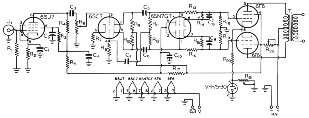
Fig. 1. Circuit diagram of the low-power modulator using a cathode-follower driver.
| C1,C8,C9 | 25 µF 50 volt electrolytic. |
| C2,C4 | 0.5 µF paper. |
| C3 | 0.0022 µF mica |
| C5,C6,C7 | 0.01 µF paper. |
| C10 | 8 µF 450-volt electrolytic. |
| R1 | 1 MΩ, ½ watt. |
| R2 | 1.5 kΩ, 1 watt. |
| R3,R8 | 2.2 MΩ, 1 watt. |
| R4,R9,R10 | 470 kΩ, 1 watt. |
| R5 | 47 kΩ, 1 watt. |
| R6 | 2 MΩ potentiometer. |
| R7 | 3.3 kΩ, 1 watt. |
| R11 | 4.7 MΩ, ½ watt. |
| R12 | 6.8 MΩ, ½ watt. |
| R13,R15 | 220 kΩ, ½ watt. |
| R14,R15 | 1 kΩ, 1 watt. |
| R17 | 5 kΩ, 10 watts. |
| R18,R19 | 10 kΩ, 1 watt. |
| R20 | 400 Ω, 10 watts. |
| R21 | 1.5 kΩ, 50 watts (adjustable). |
| R22 | 10 kΩ, 10 watts (adjustable). |
| T1 | Output transformer. |
To compensate for the voltage drop through the load resistors in the cathodes of the 6SN7, the voltage of the biasing source must be higher than that required for biasing purposes. Plenty of plate voltage was available for the 6F6s since they are operated from the same plate supply as the 807. For this reason cathode biasing was considered, but the varying plate current of the 15 Watt Modulator 6F6s made this system of biasing impractical without some form of regulation. The cathodes should be about 80 volts above ground and the grids 60 volts. A 25-per-cent swing in plate current would vary the cathode potential over 20 volts which would either double the bias or reduce it to zero which definitely would not do. The problem was solved by the addition of a VR-75-30 to regulate the cathode voltage of the 6F6s. The current limits of this tube are just about right to accommodate the difference between the resting and maximum-signal values of cathode current. A conventional 6SJ7 pentode and a 6SC7 phase inverter provide plenty of gain to drive the 6SN7.
The only difficulty experienced in getting the circuit to operate properly was in the adjustment of modulator bias. This is affected to a great extent, of course, by the plate current of the 6SN7 flowing through its cathode load resistors. Bias may be adjusted by changing the value of either R17 or R20. It is quite probable that the 400-ohm value specified for R20 is as high a value as one would want to use because of the reduction in regulation when this resistance is high.
Notes
Bernard H. Geyer, JR., W8WGF/1.