Home - Techniek - Electronica - Radiotechniek - Radio amateur bladen - QST - Put 'em push push!
A low-cost way to get started on 6.
Operation in the 6-meter band offers many interesting possibilities, yet many refrain from using this band because they think that it entails the construction of a new rig, or a rebuilding of the existing one. Here W9GUP shows a simple outboard u nit which should make it possible for anyone now having a 10-meter rig to put a signal on 6.
Then the 50-Mc. band was released we began to look over the ways by which we could get a signal on that band without a complete rebuilding job on the existing 10-meter rig. We didn't want to use a conventional doubler, as we knew that modulating such a stage would be sure to bring in QSLs of the wrong kind. The push-push doubler idea looked better, but changing the existing 10-meter final from push-pull to push-push was not easy. The simplest solution seemed to be an outboard push-push doubler, to be driven by our regular 10-meter rig.
Excitation for this stage could be supplied by the present 10-meter rig, with no greater trouble than a change of crystals and a slight retuning. Our line-up is similar to litany ten-meter jobs now in use: 6L6 crystal oscillator-doubler, 807 doubler, and push-pull 807s in the final. The oscillator uses 7-Mc. crystals. Substituting 6.25-Mc. rocks and retuning the circuits slightly gave us 25-Mc. output from the 807s without any pruning. As most hams design their tank circuits so that they tune "all out," almost any rig will have enough tuning range to take care of 25 as well as 28 Mc. without alteration. The push-pull 807s provide more than enough drive for a push-push doubler using any of the low-C triodes.
A glance at the schematic, Fig. 1, will show the simplicity of such an arrangement. Since neutralization is not required, a compact layout is possible, and the unit described has room to spare on a 7 × 13-inch chassis. The tubes employed are 3024s, or 24Gs, but any low-C triodes may be used. The grid circuit is similar to any push-pull amplifier, but the two plates are connected together and a single-ended circuit which resonates at 50 Mc. is used here. Excitation, which is on 25 Mc., is fed to the grids by means of a twisted-pair link not shown in the photograph. The porcelain stand-off near the grid coil serves as a support for the link. Two turns of insulated wire around the center of the grid coil will provide more than enough coupling to the driver stage. Output is taken from the 50-Mc. plate circuit by means of a two-turn link, which is inserted between the turns of the tank coil at its cold end. This link is connected to two feed-through bushings which are mounted on a polystyrene plate at the end of the chassis. The filament transformer, tube sockets, two r.f. chokes, and a small bias battery are mounted below the chassis. The bias battery is a good precaution, to save the tubes in case of excitation failure, and it permits use of the rig on c.w. by means of keying a preceding stage.
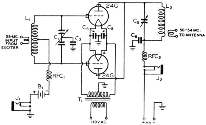
Fig. 1. Schematic diagram of the 50-Mc. outboard push-push doubler.
| C1 | 35 pF-per-section split stator. |
| C2 | 35 pF, double spaced. |
| C3 | 0.008 µF mica. |
| C4,C5 | 0.0022 µF mica. |
| C6 | 0.002 µF mica, 2000-volt test. |
| L1 | 12 turns center-tapped, No. 20 enameled wire, spaced 1 inches on a 1X-inch diameter polystyrene plug-in coil form. Coupling link (not shown in photograph) is 2 turns of insulated wire around center of L1 |
| L2 | 5 turns No. 14, 1-inch diameter, spaced 1¼ inches; self-supporting and mounted directly on the plate condenser. The antenna pick-up coil is two turns No. 18 push-back wire, 1-inch diameter, at cold end of L2. |
| B1 | 45 volt battery. |
| J1,J2 | Closed-circuit jack. |
| RFC1 | 2.5 mH r.f. choke. |
| RFC2 | Six-meter v.h.f. radio-frequency choke. |
| T | Filament transformer, 6.3 volts a.c. at 6 amperes, for 24Gs. |
Two closed-circuit jacks are mounted on the front of the chassis, one for measuring the grid current and one for plate current. The latter also serves as a means of applying modulation. A patch cord is connected to the secondary of the modulation transformer, and this is plugged into the plate-meter jack when the rig has been tuned up and is ready for modulation.
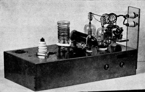
The 50-Mc. outboard amplifier has room to spare on a 7 × 13-inch chassis. The stand-off at the left serves as a mounting for the link from the driver stage. The single-ended plate circuit and antenna coupling are at the right. Jacks on the front of the chassis provide for insertion of grid and plate milliammeters.
Tuning up
With excitation applied to the grids and a 100 mA meter inserted in J1, tune the grid condenser, C1, for maximum grid current. This should be at least 50 mA. Plate voltage may then be applied, starting with 400 volts or so. Tune the plate condenser, C2, for minimum plate current. It is well to remember that, as this stage is operating as a doubler, the dip will not be as pronounced as with a straight amplifier. A calibrated absorption-type wavemeter should be used at this point, to be certain that the output is on the desired frequency.
I wanted to use the same modulator for 6 as for 10, hence it was necessary to run about the same input on both bands. With 400 volts on the plates, input to the 3C24s runs about 180 ma., with the antenna coupled. Much higher voltages may be used on the final if the audio power is available to modulate the increased input. With higher plate voltages it would be advisable to insert a resistor of about 2000 ohms in series with the bias battery, to bring the bias up to the 125 volts recommended for the 3C24s. Somewhat more grid drive will be required, but higher efficiency will result than is obtainable with the low voltage on the plates.
Other possibilities
This set-up is designed for crystals in the range between 6.25 and 6.75 Mc., but if your rig uses 14-Mc. crystals for 10-meter operation, 12.5-Mc. crystals can be used for 50-Mc. work by the process outlined above. The 6.25-Mc. rocks have the advantage of being plentiful and cheap, crystals in this range having been used extensively in war-time applications.
If you want to go "whole-hog" on 6, the use of f.m. presents an interesting possibility. By using the same outboard amplifier technique, it is possible to add a high-powered 6-meter final to any 10-meter rig, and the use of f.m. keeps the over-all cost low. Such a rig would also be useful for DX c.w. work when band conditions are hot.
So there you are - it's not so tough to get started on 6. A cheap crystal, and an outboard amplifier made up from parts most of us have kicking around, will do the trick. Warm up the old soldering iron and put 'em in push-push - I'll be seeing you on 6, neighbor!
Louis J. Frenkel, Jr., W9GUP.