Home - Techniek - Electronica - Radiotechniek - Radio amateur bladen - QST - Matching the line to the ground-plane antenna
Design data for coax feed.
By proper predimensioning of the antenna and shunt corrective stub, a proper match to practical coaxial-line impedances is assured with the ground-plane antenna. The necessary dimensions can be determined by a few simple calculations.
The ground-plane antenna,(1) consisting of a vertical radiator approximately a quarter wavelength long extending above four ground radials at right angles to the antenna, together with a supporting-and-matching stub, has been described in QST.(2) Herewith are some data which are useful to those building such antennas.
When used with four ground-plane radials a quarter wavelength long the antenna (vertical section) is resonant when its length is about 89 degrees with the matching stub disconnected. When this condition obtains, the antenna impedance is a pure resistance of about 24 ohms.(3) Since the usual transmission line has an impedance greater than this, some system of impedance transformation must be applied so that the resonant antenna resistance, Rr, as seen by the transmission line is the same as the characteristic impedance, Z0, of the transmission line. If we desire to feed the antenna with a coaxial line having a characteristic impedance of 50 ohms, for example, we must make Rr equal to 50 ohms at the resonant frequency.
Practically, this can be done in two ways. We can connect between the antenna-system feed point and the transmission line a quarter-wave section of matching line whose characteristic impedance is equal to the geometric mean of the antenna resistance and the transmission-line characteristic impedance, Z°. This is the so-called "Q" matching system. Incidentally, the supporting stub could be' replaced by this quarter-wave concentric matching line, the shorting plug at the bottom being omitted and the concentric transmission line connected in its place. This is a good arrangement if it is desirable or convenient to suspend the entire antenna system by the upper end of the vertical antenna section.
Another approach to the impedance-matching problem is to reduce the length of the antenna (vertical section) slightly so that at the operating frequency the antenna impedance is composed of both resistance and capacitive-reactance components, Rs and Xs respectively, and then shunt the antenna feed point with an inductive reactance that brings the system back to resonance. When this is done the antenna impedance is a pure resistance and will have a value different from the self-resonant value. The equivalent circuit is shown in Fig. 1. Suppose, for example, the antenna length is reduced so that, in Fig. 1, Ra = 18.4 ohms and Xs becomes 31 ohms capacitive. Then Za = Ra - jXa = 18.4 - j31 ohms. Suppose we connect across this an inductance so that Xs = +j41 ohms. Then Rr in Fig 1 is found by:
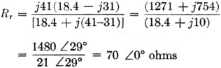
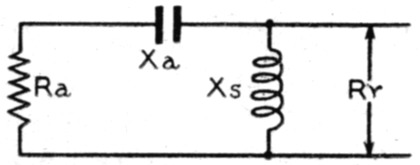
Fig. 1. Equivalent circuit of the antenna and match. ing stub. The shortened antenna appears as a capacitive reactance, Xa, in series with a radiation resistance, Ra. With a shunting inductive reactance, Xs, of the proper value the system appears as a purely resistive load, Rr, having a value determined by Ra, Xa and Xs.
In the application of the ground-plane antenna some means of supporting the structure must be provided. If it is not desired to transform the antenna resistance, the antenna can be supported upon a quarter-wave section of coaxial line. In this case the line acts as a metallic insulator, because if the lower end of the line is shorted the end connected to the antenna presents a very high impedance and acts the same as.though we had a 'radio-frequency choke connected across the antenna feed point, where the antenna impedance is very low relative to the line impedance the point of attachment. In practice, the suprt stub is a section of rigid coaxial line with the ttom end shorted; the ground-plane radials connected to the top of the outer conductor and the antenna is simply an extension of the er conductor. When the antenna is supported a quarter-wave section shorted at the bottom, and whose function is only that of mechanical support, the characteristic impedance, Z, of the supporting stub is not important generally, since the impedance will nearly always be much greater than the antenna impedance.
However, when the support stub is shortened for impedance matching, a characteristic impedance of about 41 ohms is desirable because the length of a stub of this impedance is found to be almost constant over quite a range of matching conditions.(3) To give an idea of the dimensions of a 41-ohm concentric line, the ratio of the inside diameter of the outer conductor to the outside diameter of the inner conductor should be 1.982/1. Incidentally, a line having an outer conductor of two-inch water pipe and an inner conductor of ¾-inch water pipe yields a line whose characteristic impedance is nearly 41 ohms. The inside diameter of 2-inch water pipe is given as 2.067 inches and the outside diameter of ¾- inch pipe is given as 1.050 inches.(4) The general idea of the construction, and the important dimensions, are shown in Fig. 2.
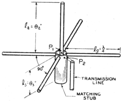
Fig. 2. Construction and important dimensions of the ground-plane antenna. The inner conductor of the transmission line is attached at P1 and the outer conductor at P2. The inner conductor in the matching stub is shorted to the outer conductor at the bottom. Below this point the support can be an extension of the outer conductor.
By supporting the ground-plane antenna with a coaxial stub as shown in Fig. 2, we can, by shortening the antenna somewhat and also shortening the support stub a certain amount, make the feed-point resistance, Rr any value we want between practical limits of say 25 to 100 ohms, by the principle indicated in Fig. 1. Here the length of the support stub is adjusted so that it furnishes the required inductive reactance, Xs, of Fig. 1.
To simplify and generalise the design of the system, equations are presented herewith which make the design of this type of antenna a "one-two-three" procedure. These are presented in the correct order for the usual case. They are:
(1) The length of one electrical degree ld is:
![]()
where fMc. = resonant frequency in megacycles.
(2) The length of each of the four equally-spaced ground radials, lg, measured from the inside of the outer stub conductor to the end, should he:
![]()
(3) The length of the antenna (vertical portion measured from the upper end of the outside conductor of the stub) in electrical degrees, Φa, for matching lines with Zo between 25 and 130 ohms, is found by
![]()
For convenience, this equation is plotted as curve A in Fig. 3. The physical length of the antenna, la, will be:
![]()
(4) When the antenna length is Φa degrees and each of the four ground-plane radials is 90° long, the resistive component of the antenna impedance, Ra, can be found by:
![]()
(5) Capacitive-reactance component Xa of the antenna impedance, for an antenna length of Φa degrees and ground-plane radials 90° long will be:
![]()
(6) Knowing Ra and Xa, we can find the required value of shunting inductive reactance, Xa, required for resonance by:
![]()
All values taken positive. This equation is plotted as curve B in Fig. 3.
(7) The characteristic impedance, Zos, of the supporting stub, when the insulation is air, is given by:
![]()
where
D = inside diameter of outer conductor
d = outside diameter of inner conductor
(8) The length of the matching stub, Φa degrees, is then:
![]()
For the case where Zos = 41 ohms, Φa is plotted in Fig. 3 as curve C. The physical length, lg, of the stub is:
![]()
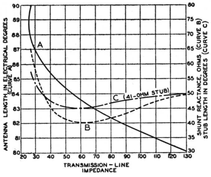
Fig. 3.
A - Antenna length, in electrical degrees, required for matching to lines of various impedances by the shunt-reactance method.
B - Inductive reactance required for matching.
C - Length of shunting inductive stub in electrical degree when the stub characteristic impedance is 41 ohms.
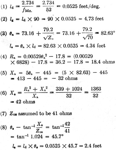
As an example of the application of Equations 1-8, assume we wish a ground-plane antenna designed for a frequency of 52 Mc. and wish to feed it with a 10-ohm coaxial transmission line. We are to match this line to the antenna by adjusting the antenna and stub length to effect the required match. We will assume a stub characteristic impedance, Zos, of 41 ohms.
Solution:
If we had desired to support this antenna on a quarter-wave stub and match it to the line with a quarter-wave matching section we would find the impedance of this matching stub by Zom = √(ZaZg) which for the 70-ohm line assumed would be: Zom = √(24 × 70) = √1680 = 41 ohms. (Since the antenna is naturally resonant when its length is 89° and has a value of Rr = 24 ohms).
The length of the ground radials will be 90 degrees as before and the length of the antenna will be:
![]()
The stub length would be:
![]()
If desired, the antenna could be hauled up by attaching to the top of the antenna as previously mentioned, using the above matching section instead of the supporting stub, attaching the coaxial feed line at the bottom end of the matching section.
Generally, it is more desirable to match the antenna by stub and antenna shortening rather than by the "Q"-section method, since this eliminates the extra section, makes the mounting stub shorter, and permits mounting directly upon a metal flagpole.
In addition, as shown by curve C in Fig. 3, the stub length can be fixed, in practice, and adjustment of the antenna length will permit matching to lines of impedances ranging from 40 to 80 ohms. Also, this allows a wider frequency response, provided the characteristic impedance of the matching stub is properly chosen. The frequency response width will also be affected somewhat by the diameter of the elements used for the vertical section and ground-plane rods, being greater for the larger diameters.(5)
Notes
- Brown at Epstein, "An ultra-high-frequency antenna of simple construction," Communications, July, 1940.
- E. Dillon Smith, "Ground-plane antennas," QST, August, 1945.
- "Back talk," Electronics, December, 1943. Data from experimental measurements at 80 Mc. on an antenna 5/8 inch in diameter. Slight modifications are to be expected with antennas having a different diameter/length ratio.
- Eshbach, Handbook of engineering fundamentals, John Wiley tic Som, Inc. (Pipe table.)
- Terman, Radio engineer's handbook, McGraw-Hill Book Co., Inc., 1st edition, p. 863, "Wide-band antennas."
John T. McWatters, W2CBK.