Home - Techniek - Electronica - Radiotechniek - Radio amateur bladen - QST - Spurious transmitter radiations
Some causes and possible remedies.
With the return of the full amateur bands the problem of confining radiations to the desired operating frequency becomes increasingly important. W3VQ points out that harmonic radiations are not the only radiations of a spurious nature to be expected from a transmitter, especially multistage v.h.f. rigs. He shows how these may be reduced by taking suitable precautions.
It has long been generally recognized and accepted that radio transmitters will radiate at frequencies which are harmonics of the final output frequency of the transmitter. But often there are other spurious radiations from a transmitter - and responses in a receiver - which are not generally recognized. These radiations may be caused by harmonics of the oscillator, and their frequencies are usually close to or actually below the desired operating frequency. When an oscillator frequency is multiplied in order to arrive at the correct final frequency, it is easily possible that some harmonics of the master-oscillator frequency will be produced which fall outside amateur bands, both above and below the desired output frequency.
When the final amplifier is modulated, it is not always possible to identify the station which is radiating on spurious frequencies. Transmitters in which the oscillator is keyed, however, are frequently cited by FCC for radiating on incorrect frequencies. A recent test of a well-constructed transmitter incorporating the latest engineering developments indicated that the harmonic output of the last tripler stage on 2/3, 4/3, and 5/3 of the operating frequency is only about 30 db. below the strength of the desired carrier.
It is widely assumed that frequency multiplication produces only the desired output from each stage. This is an incorrect assumption which makes no allowance for the possibility that new frequencies, not expected to be produced by the multiplier, may appear in the output of the final stage. This may be the result of undesired coupling between the oscillator and final amplifier, or between other stages. To illustrate this point, consider a transmitter having a total frequency multiplication of 16 (that is, 2 × 2 × 2 × 2). It would be possible for the adjacent 17th harmonic of the master oscillator to appear in the output, although it might not be expected because it can be obtained only by a large multiplication of the frequency of the master oscillator (1 × 17). How. ever, if r.f. energy from the master oscillator leaks into the final amplifier, it may very possibly modulate the output of the final amplifier. This would produce an output on both the adjacent master-oscillator harmonics which would be the 15th and 17th.
Harmonic spacing
An investigation of some of the characteristics of frequency multipliers may help to understand this situation better. If the frequency multiplication in a stage is greater than two, undesired harmonics of the driving stage are relatively close to the desired frequency and the tuned circuit presents sufficient impedance to enable the generation of appreciable power. If a multiplier doubles, the nearest undesired harmonic is the 3rd, which is 50 per cent higher in frequency, and the fundamental, which is 50 per cent lower. If a total multiplication of 6 is desired, this doubler might be followed by a tripler. The doubled output of the first tube is then amplified in the second tube whose output circuit is tuned to present a high impedance to the 6th harmonic of the master oscillator. Close study will show that the tripler may also have in its output the 4th and 8th harmonics of the master oscillator by also doubling and quadrupling its input.
The grid of the tube following the tripler will receive the output of the second multiplier, together with any of the second-harmonic input which reaches it. These may intermodulate, just as in a mixer tube, to produce the 6th harmonic plus and minus the 2nd harmonic, creating 4th-and 8th-harmonic power.
Before going further, let us examine the harmonic spectrum from the doubler. Its 5th harmonic relative to the oscillator frequency should have been greatly attenuated by its tuned circuit. However, the second tube is a relatively-efficient straight-through amplifier for this frequency inasmuch as its plate circuit, tuned to the 6th harmonic, is resonant at a frequency which is only 20 per cent higher than this 5th harmonic.
The result is that multipliers produce power of different amounts at essentially all harmonics of the original oscillator frequency. This is illustrated in Fig. 1, which shows that harmonics present in the oscillator itself may also reach the final output circuit by spurious coupling or trough the multipliers. The oscillator harmonics y be amplified, and appear through more than e combination of multiplications. Obviously, 5th and 7th harmonics should be weak since ey are either leakage products of the harmonics of the oscillator, or are generated in the final output by the modulation of the 4th, 6th, or 8th harmonics by oscillator-frequency energy which has reached the circuit through spurious coupling.
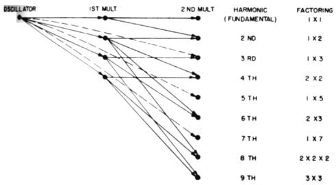
Fig. 1. Diagram showing how harmonics of the oscillator may reach th output circuit through stray coupling.
Reducing unwanted radiation
Several means of reducing the power developed at the undesired frequency can be applied during the design of the equipment. In general, it would appear to be best to select an arrangement in which the output frequency may be factored into a number of small digits. That is, multiplications to 16 or 32 might be desirable because they may be reached by successive multiplications by two, without requiring multiplication by three or a larger number. For example, a multiplication of 15 could be obtained by 5 × 3, but probably would be less desirable than 16 which could be reached by 2 × 2 × 2 × 2, especially since the output at the desired frequency would be better in the latter case.
Ordinarily, multipliers are designed for the reduction of maximum power at the desired utput frequency. Where the production of spurious frequencies is to be reduced to a minimum, however, the number of tuned circuits, loading, and selectivity also become important because they control the power produced by undesired multiplications. Unfortunately, inasmuch as all harmonics of the oscillator may appear hi he multiplied output, large multiplications are undesirable because they offer less opportunity to suppress all but the intended output frequency. This is because, on a percentage basis, adjacent harmonics are close in the case of a multiplier of higher order. For example, if the 4th harmonic of the oscillator is desired as the output frequency, the adjacent 3rd and 5th are 25 per cent away in frequency. On the other hand, if the 32nd harmonic of the oscillator is desired, the 31st and 33rd are only about 3 per cent removed in frequency. Also, large multiplications in individual stages limit the number of selective circuits available to suppress the undesired harmonics.
Table 1 shows the measured output from an Army frequency-modulated v.h.f. transmitter which uses high multiplication of a low-frequency oscillator. In attempting to improve the situation, the first step was to use a much higher oscillator frequency, with less multiplication. This provided a wider separation between the desired harmonics and those next adjacent above and below the output frequency, as shown in the third column, and this resulted in improved attenuation through the normal selectivity of the multiplier tuned circuits. The table also shows in the last three columns the measured attenuation of the undesired harmonics using several types of multipliers. In this instance, 4 × 1 × 2 produced better attenuation than 2 × 2 × 2, presumably because the straight-through or buffer stage allowed the use of the same number of tuned circuits and was not overbiased, which may have tended to reduce the harmonic content of the power passing through it. Undesired coupling in the set will account for other peculiarities.
| Frequency | Harmonics in originaltx with 1,25 Mc. crystal |
Harmonics in revised tx with 6 Mc. crystal |
Harmonic output from original tx |
Harmonic output from Revised Transmitter | ||
|---|---|---|---|---|---|---|
| 4 × 2 multiplying |
4 × 1 × 2 multiplying |
2 × 2 × 2 multiplying |
||||
| 33.75 | 27th | 82 dB | ||||
| 35.00 | 28th | 7th | 51 dB | 80 dB | 76 dB | 70 dB |
| 38.25 | 29th | 52 dB | ||||
| 37.50 | 30th | 45 dB | ||||
| 38.75 | 31st | 28 dB | ||||
| 40.00* | 32nd | 8th | 0 dB | 0 dB | 0 dB | 0 dB |
| 41.25 | 33rd | 33 dB | ||||
| 42.50 | 34th | 53 dB | ||||
| 43.75 | 35th* | 56 dB | ||||
| 45.00 | 36th | 9th | 59 dB | 71 dB | 84 dB | 72 dB |
| 46.25 | 37th | 75 dB | ||||
* Desired output frequency.
Table showing spurious-frequency output from experimental transmitter (resistive termination) in dB below carrier.Push-Push & Push-Pull
It is generally expected that the harmonics of the final amplifier or last multiplier stage will be relatively strong. Othe. expected harmonics of the oscillator may or may not be strong, depending upon the stray coupling within the multiplier; some expected frequencies may be very strong whereas others may be weak, depending on whether the stray coupling aids or bucks the power coming through the multiplier tubes.
"Push-push" amplifiers are frequently used for doubling and quadrupling. They give the tuned circuit an impulse twice in the same direction for each input cycle; therefore, they tend to suppress the odd-harmonic output. Similarly, push-pull multipliers may be used as tripiers, in which case, if the output from each tube is carefully balanced, the impulse from the second tube tends to cancel power from the first tube on the even harmonics, such as the second and fourth.
Crystal-controlled and a few other types of receivers use multiplication from a low-frequency oscillator in order to obtain mixer injection voltage. Because of the presence of undesired harmonics of the original oscillator frequency, aggravated by a tendency to overdrive the mixer, such receivers are likely to respond effectively to frequencies other than the one to which the receiver is tuned, unless the r.f. stages and shielding are very effective in preventing such frequencies from reaching the mixer stage. This condition is in addition to the better-known difficulties with images and r.f. drive-through.
Conclusions
In order to reduce the probability of operation on undesired frequencies, several features should be brought into consideration by the designers of transmitters and receivers, such as:
- Minimum multiplication, using a high-frequency oscillator. Especially interesting in this respect are the new Western Electric CR-9 harmonic crystals in which the first tuned circuit operates up to 50 Mc. The circuit might be described as a "neutralized Tri-tet with a crystal gate."
- The selection of an oscillator frequency which permits multiplication of not more than 2 or 3 in a single stage.
- The use of many tuned circuits, each lightly loaded, so as to retain a high degree of selectivity. Broad-band and bandpass circuits are less desirable in this respect.
- Reduction of leakage output from multiplier stages, not only into power lines and other radiating media, but also into the output amplifier itself. The use of interstage shielding to reduce stray coupling is indicated.
- Use of push-push or push-pull multiplier stages where applicable in an attempt to reduce the output on the even or odd harmonics adjacent to the desired multiplication by careful balance.
Most of the features listed above are strictly a matter of design. However, the amateur can aid materially in suppressing spurious radiation by careful alignment and balance where they apply, provided that these factors are made variable.
E.H. Conklin, W3VQ.