Home - Techniek - Electronica - Radiotechniek - Radio amateur bladen - QST - Multielement radiators in close-spaced arrays
Reducing losses and increasing frequency tolerance in three- and four-element beams.
Because of the great difference between the impedance of a spaced line and that of the usual multielement array, those using antenna systems of this type are faced with the choice of a spaced line with losses in the matching section or a less efficient type of line. Also, a low-impedance antenna system is critically dependent upon frequency and difficult to adjust. By the use of a multiwire radiator, the antenna impedance may be increased to the point where the radiator may be fed directly with a conventional open-wire line and - probably of greater importance - the array becomes more tolerant as to frequency and easier to adjust.
The problem of feeding close-spaced parasitic beams with flat or untuned lines may be approached from two 'different points of view. An impedance-transforming device such as the delta, the "T," or the quarter-wave matching section may be used between the line and the array, or the effort may be directed at increasing the radiation resistance of the antenna by various means, such as the use of greater element spacing, or of a folded doublet as the radiator.
The slightly-higher theoretical efficiency possible with antennas of reasonably-high radiation resistance is probably not significant. However, since the antenna impedance approaches more closely that of a spaced line, this more efficient type of line may be used with less loss in the matching section; in fact, if the antenna impedance is made sufficiently high, the matching section with its confusing adjustments may be eliminated entirely, even with close-spaced arrays. What is probably more important to the amateur, however, is the fact that as the antenna impedance is increased, the system becomes more frequency-tolerant so that it works efficiently over a larger portion of the band.
The multiple doublet, folded dipole, or cage doublet, as it is variously called, consists of a simple half-wave antenna and one or more elements parallel to it connected only at the ends, as shown in Fig. 1. If such a multielement doublet is substituted for the simple dipole in the conventional close-spaced beam, the radiation resistance of the antenna will be multiplied by the square of the number of elements in the folded doublet. For example, if we consider the radiation resistance of the three-element beam to be 9 ohms, and if the simple dipole is replaced by a three-element folded- doublet, the new array will have a radiation resistance of 32 × 9, or 81 ohms; if the radiator is a four-element folded doublet, the radiation resistance becomes 42 × 9, or 144 ohms, etc. For the antenna system to match the highly-efficient open-wire line, the radiation resistance must be of the order of 400 ohms or more. This necessitates the use of at least seven elements in the radiator to give a theoretical radiation resistance of 72 × 9, or 441 ohms.
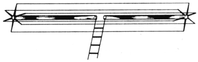
Fig. 1. Sketch showing the essential plan of constructing a multielement cage antenna for use as the radiator in a close-spaced array.
Such an antenna has been in use here at W4GCA/9 for some months and has been completely satisfactory. The present form of the antenna is the result of a series of experimental antennas with different feed lines and different numbers of elements in the radiator. As a final test here, a second antenna was built to see that results could be duplicated in another installation. Finally, the antenna has been copied by several other amateurs, and in every case which has come to the author's attention, the results were as predicted.
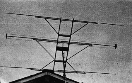
A three-element rotatable antenna with multielement radiator in use at W9BIQ.
Element dimensions
The characteristics of the antenna may be summarized as follows: With no change in link coupling to the final, the loading is quite uniform from 28,500 to 29,700 kc. (5-to-15-per-cent variation); the forward gain throughout the ten-meter band is practically constant as based on comparative signal reports on widely different frequencies on ground-wave, normal and DX contacts; the pattern remains unaltered throughout the band, as based on front-to-back and frontto-end ratios reported in numerous contacts, both local and DX; the reactance introduced by the antenna is low throughout the band and is negligible at the resonant frequency of the antenna; the parasitic elements determine the resonant frequency of the system to a large extent so that it is not necessary to provide means for changing the length of the radiator for tuning purlioses, and the tuning of the parasitic elements is not at all critical.
The following formulas have been used by the author and with equally good results in other installations:
![]()
decreased by twice the diameter of the cage.
![]()
spaced 0.1 wavelength from radiator.
![]()
spaced 0.15 wavelength from radiator. All spacing dimensions are center-to-center.
The radiator consists of ½ inch tubing, paralleled with six No. 12 wires spaced 4 inches from the center of the tubing, arranged symmetrically around it and connected only at the ends, as shown in Fig. 1. The tubing is separated 2 inches in the center for a 2-inch line. The size of the tubing and wire and the spacing between wire and tubing are not critical. Various construction methods may be used to furnish support for the wires. The author uses small rods, 8 inches in length, arranged like spokes of a wheel, at each end of the tubing. A disc or six-pointed star welded to the ends of the tubing is equally satisfactory. These details are sketched in Fig. 2. Some means of support should be used about one-third of the distance in from each end. Insulators should be of polystyrene or some other good h.f. material.
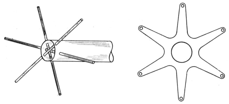
Fig. 2. Details of two types of metal wire-element spacers which are fitted on the outer ends of the tubing element as discussed in the text.
If the parasitic elements are set to give a fundamental frequency between 28,600 and 29,000 kc., the antenna will give good results throughout the band as well as fair efficiency on 11 meters.
The method of determining the effect of replacing a simple dipole with a multiwire doublet on the radiation resistance is largely empirical. However, on the basis of the various combinations used here and the results obtained by others who have tried the same general method, it seems that the formulas do work out for the case of closespaced beams at least. They are also verified in the ease of a long wire used as a reference antenna, where the end half-wave is fed as a folded doublet which presents a very good match to. a 470 ohm line.
Number and size of radiator elements
The following table gives suggested radiators for three- and four-element close-spaced arrays using some of the common line impedances met in practice.
| Lines impedances in Ohms | Elements in radiator | |
|---|---|---|
| Twos Parasitics Elements | 72 | 3 |
| 150 | 4 | |
| 300 | 6 | |
| 500 | 7 | |
| 600 | 8 | |
| Threes Parasitics Elements | 72 | 4 |
| 150 | 7 | |
| 300 | 8 | |
| 500 | 9 | |
| 600 | 10 |
In general, the higher the radiation resistance, the broader the frequency response, so that some of the beams with lower radiation resistance will not have the same characteristics as described above. The ARRL Handbook suggests the use of two elements of different sizes ina folded doublet to obtain an increase in radiation resistance of more than 4 to 1. There is a feeling on the part of some amateurs that the increase depends entirely on the ratio of the diameters of the two elements. My first sketchy experiments did not show progress in that direction so that method was discarded because of negative results. I understand, however, that some work along that line has been done recently by others. It is my guess, based on admittedly inconclusive experimental data, that the increase in radiation resistance obtainable by such a method will involve not only the ratio of the two diameters but also the spacing between them, and that no great difference will be observed unless the spacing between elements is less than the diameter of the larger element. A possibility which looks interesting is the use of a semicircular trough as the paralleling element with the driven element down the line of centers of the semicircular cross-sections. Again, a guess would be that such a set-up would introduce a high capacitive reactance.
Adjustment
A word or two about tuning the beam might be useful. It will be found that the parasitic elements are much less critical in adjustment than the conventional close-spaced beam. The formulas shown seem to give optimum forward gain, though a slight improvement in front-to-back ratio may be possible with readjustment with no sacrifice in forward gain. If tests are to be made for adjustment purposes, it is suggested that the parasitic elements be cut to length by formula, and then adjusted with a field-strength meter to attempt to get additional forward gain. (The antenna presently in use has not been tuned.) Then, adjust the reflector only for maximum front-to-back ratio, and recheck to see that there has been no loss in forward gain.
The following is a summarized table of a series of tests made over an extended period of time in ground-wave, normal and DX contacts. The reference antenna is a long wire of nine full wavelengths, current-fed by folding back an additional half-wave at one end and center feeding this halfwave with an open-wire line.
| Freq. (Mc.) | S-Meter readings | Standings wave ratio | |||
|---|---|---|---|---|---|
| Ref. Ant. | Beam | ||||
| Front | Side | Back | |||
| 28.52 | 9 | 9 + 30 | 6 | 9 | 1.9 : 1 |
| 29.05 | 9 + 10 | 9 + 30 | 5.5 | 8 | 1.4 : 1 |
| 29.69 | 9 | 9 + 15 | 4.5 | 7 | 1.7 : 1 |
The link coupling to the final was not changed for the beam for the three frequencies indicated. It was necessary to change the link coupling for the long-wire antenna in order to keep the input the same, however.
The transmitter uses a pair of VT-127s in the final with 2200 volts on the plates. The beam antenna is about 50 feet above the ground mounted above the roof of the house on a two inch pipe. The pipe extends about 16 feet above the roof of the house and there is probably some excitation of that 16 foot section, resulting in the radiation of some vertically-polarized energy. The discrimination, both front to back and front to end, has proved better in some of the other antennas of this type that have been built to the specifications used here.
I do not believe that such tests as are summarized in the above table are of more than nominal value in determining the worth of an antenna. The only method which seems to indicate the merit of an antenna is its actual performance over an extended period of time. Such results are not subject to being summarized or tabulated, but they were of such nature as to be quite satisfactory here and have led to numerous questions about the installation from those who have heard and worked us.
G.N. Carmichael, W4GCA/9.