Home - Techniek - Electronica - Radiotechniek - Radio amateur bladen - QST - Choosing a transmission line
A comparison of various types of feeders.
A complete discussion of the amateur's problem in choosing a feed system for the transmitting antenna, or more properly the transmit-receive antenna, could contain a great many practical examples and consume far more space than that usually allotted to a single article. Therefore it is the purpose of the author to dwell on fundamental considerations only, leaving it to the reader to apply the fundamentals to his own immediate problems.
The transmission line may take several forms. The most commonly used, by virtue of its low loss and low cost, is the open two-wire line separated by insulating spacers. A popular recent variation is Amphenol's Twin-Lead, in which a good part of the dielectric between the wires is polyethylene rather than air. Another form of transmission line is the coaxial cable in which the fields are confined within the outer conductor. Coaxial cables are manufactured with air or dry gas under pressure as the principal dielectric, or with a solid dielectric such as polyethylene. A now seldom-used feeder is the single-wire type in which we depend on the ground as the "return" side of the circuit.
The amateur's choice. of a feeder system is frequently dictated by the cost and by the availability of construction and design information. It is for the latter reason that most of us have almost automatically chosen the two-wire air-spaced feeder, although in doing so it happens that we have picked the system which gives the lowest inherent loss under conditions of incorrect adjustment. The ARRL Handbook contains much useful information on the design of two-wire air-spaced feeders either for untuned operation or as part of the resonant antenna system.
Twin-lead for transmitting
The recent development of Amphenol Twin-Lead has provided a new convenience in putting up a two-wire feed system. But use of the present receiving-type Twin-Lead necessitates certain precautions which could be neglected with the air-insulated line. Twin-Lead should not be used as a tuned feeder. Why? Because in a tuned resonant system the current at every current loop along the line wire, with moderate power, is high enough actually to heat the conductors, which are equivalent to No. 20 solid wire, and heat in the line is not what we need to work DX. With an untuned line, carefully matched to the load, Recent years have brought a considerable quantity of solid-dielectric r.f. transmission lines onto the market. This article should serve to clear up some of the confusion which exists in the minds of many hams as to their limitations, advantages and proper application.
the current for 500 watts will be approximately 1.3 amperes for the 300-ohm line, 1.8 amperes for the 150-ohm line and 2.6 amperes for the 75-ohm line. Remember that this applies only to the matched line in which the current and voltage are constant at all points. By comparison, a 2-inch spaced air line made with No. 12 wire and operated untuned would carry a current of about 1.04 amperes.
As a further price to pay for the convenience of Twin-Lead, the 300-ohm line is sensitive to the effects of surface moisture. This will be treated more fully a little later, but it can be emphasized now that the effect is not penetration of the insulation by the moisture. The surface water simply joins with the polyethylene web and the air immediately surrounding the two conductors to become a part of the dielectric. This produces a change in the impedance of the line.
Personally, the author likes air-insulated two-wire transmission line for long runs, and prefers the Twin-Lead type of line for a week-end experiment where the convenience factor is a very important one. But it is believed that, as we learn how to use it more effectively, we shall all be employing coaxial transmission line in our more or less permanent installations. We need go no farther than the local broadcast, f.m. or police installation, to find coaxial cable doing an efficient job, free from weather effects and without most of the BCI problems which are all too common in our experience with wide-spaced two-wire lines. Most of us choose coaxial cable without hesitation for the v.h.f. mobile rig, although we may not stop to reason why.
Coaxial lines
The war has brought about rapid development of low-loss coaxial transmission lines in which the inferior prewar dielectric materials were replaced by polyethylene, which has loss properties similar to those of polystyrene with which most of us are familiar. Now, in a comparable size and at frequencies below 300 megacycles, the loss of a good-quality solid-dielectric coaxial cable is of the same order as that in an air-dielectric co-ax line, and most of the new f.m., television and police antennas are being fed through polyethylene-insulated solid-dielectric coaxial cables instead of the more costly and troublesome gas-filled co-ax lines. The remarks made earlier about the necessity for matching Twin-Lead apply with even greater effect to a coaxial line. A good matching job is rewarded with the finest kind of performance over a long period of time. That the matching job requires a bit more attention must be conceded, for we cannot look for standing waves along a co-ax cable with a neon lamp.
Summarizing the general discussion, we can say that our choice of a transmission line will be made after consideration of at least the following factors:
- whether the line is to be tuned or un-tuned or a combination of the two;
- the loss characteristics;
- the cost;
- the importance of weather effects; and
- the convenience or time available for the construction of the feeder system.
If the transmission line is to be tuned, the choice immediately would be the open-wire line with a spacing of not less than 4 inches and a wire size no smaller than No. 12. The Handbook does an excellent job of specifying the design and construction of tuned feeder systems. If the feeder is to be untuned, all of the other comparison factors should be examined.
For convenience, Table I has been prepared to provide comparisons in power-loss percentages, approximate amateur costs, and weather effects. It does not take into account the labor expended in construction or installation, since we are dealing with a hobby where the income per hour is of no real significance.
It will be noted that the loss values and costs are approximate, and that they are based on matched lines 100 feet long used at a frequency of 14 to 28 Mc. (for loss determination). At 3.5 Mc. the loss values are so low that they almost cease to be a factor for comparison.
Impedance matching
So much for generalities and comparisons. The line chosen must be operated efficiently which means careful matching, or in the case of the tuned line, careful balancing. To achieve best results we can profitably review the performance of all transmission lines in terms of the open two-wire line. An infinitely-long two-wire line will carry power away from the transmitter steadily and with no reaction on the output stage. It may be compared with an unobstructed water pipe draining water from a main. The pressure or voltage across the line will be a maximum at the source, and it will fall gradually as we move to the end of the line. The loss is a combination of simple IR drop and more-complicated dielectric loss. The same performance is realized with a line terminated in a pure resistance equal to the characteristic impedance of the line. If the line is not so terminated, or if it contains impedance discontinuities as a result of improper connection through a change-over relay or presence near metallic objects or poor dielectric material, reflection " kick-backs" will occur just as they may be observed in a water or steam system which "knocks."
In the case of an electrical network it is always possible to find an impedance of such value that if it is connected across the output of the network, the impedance of the entire, network, including the specific impedance connected across the output, will appear to the source as exactly equal to the impedance connected across the network's output terminals. This value of impedance is called the characteristic impedance of the network and is expressed mathematically:
![]()
where:
Zo is the characteristic impedance,
Zoc the network's impedance with the output open-circuited, and
Zsc the network's impedance with its output end short-circuited.
This is illustrated in the simple network of Fig. 1 in which
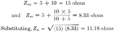
Fig. 2 shows the network of Fig. 1 with a resistance of 11.18 ohms shunted across the output end. The over-all resistance, looking into the input, will be seen to be
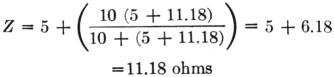
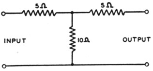
Fig. 1. Simple network.
In other words, if an impedance equal to the characteristic impedance is connected directly to the source, or if it is connected to the source by means of the network, the source will see, in either case, the same impedance.
It can be shown readily that any number of network elements such as indicated by Fig. 1 may be placed in series. The formula for Zo, the characteristic impedance, will still be satisfied, and if we make the final circuit element a network section such as Fig. 2, the source, looking into the input, will see a load of 11.18 ohms. It is essential that the electrical properties of a transmission line be uniform throughout just as the simple example used for demonstration required that all of the network elements be alike.
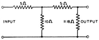
Fig. 2. Simple network with ter-r mination in its characteristic impedance.
Standing waves
In a transmission line of infinite length, the input impedance, the output impedance and the characteristic impedance are all equal. The line impedance is composed of series resistance, series inductance, shunt capacitance and shunt conductance. The finite-length lines which we use may be thought of as being made up of a large number of small units in series, each unit having values of series resistance, inductance, shunt capacitance and shunt conductance.
If a normal-length transmission line is left open at the load end, the current and voltage waves sweeping down the line from the source will encounter an infinite impedance at the open end. Since the R factor in P = I2R is essentially infinity and the I 2= factor zero at the open end, the power cannot be absorbed. It can neither remain at the open end nor disappear. Therefore, it is reflected back toward the source. The same situation with respect to reflection is found in a line terminated by a short-circuit, where the R factor in P = I2R is essentially zero. Here again, the power cannot be absorbed, and the current and voltage waves sweep back toward the source.
If the transmission line is open at its load end, the reflected wave of energy will combine with the oncoming wave of energy in a phase relationship which will provide current addition at points along the line and current cancellation at other points. For the open-ended line, the first current maximum will occur one-quarter wave back from the end of the line, and the first point of current cancellation (voltage maximum) will be one-half wave from the open end. These points of maximum and minimum current will then be repeated every half wave on toward the source. For a line that is short-circuited at the load end, the first current maximum will appear one-half wave from the load end of the line, and the first point of current cancellation will be found one-quarter wavelength from the load end of the line.
At points of maximum current, the line voltage is at a minimum, and at points of maximum voltage, the current is at a minimum. These maximum and minimum points do not change position so long as the frequency remains fixed, leading to the description of the waves which they delineate as "standing waves of current or voltage."
Complete addition and complete cancellation of current and voltage in the establishment of a standing-wave pattern are to be found only in a perfectly-tuned lossless line. Where standing waves occur on what is supposed to be an un-tuned flat line because the line is not terminated in a resistance equal to the characteristic impedance, the addition and cancellation effects may be only moderate. That is, the current measured at a maximum point may be only twice the current measured at a current-minimum point. For such a condition, the standing-wave ratio in current would be two to one.
| Transmisson Line | Power Loss in % per Hundred Feet | Approximate Amateur cost in $ | Weather effects | |
|---|---|---|---|---|
| 14 Mc. | 28 Mc. | |||
| Two-Wire Air-Spaced | 5.0 | 8.0 | 7.50 | Slight |
| 300 Ohm Twin-Lead | 11.0 | 17.6 | 3.00 | Appreciable |
| 150 Ohm Twin-Lead | 13.0 | 20.0 | 2.50 | Noticeable |
| 75 Ohm Twin-Lead | 22.5 | 35.3 | 2.00 | Slight |
| 75 Ohm Transmitting Twin-Lead | 17.5 | 27.5 | 7.20 | Slight |
| Coaxial Cables | ||||
| RG-8/U, 52 Ohms | 13.8 | 20.0 | 19.00 | None |
| RG-17/U, 52 Ohms | 5.2 | 8.0 | 88.00 | None |
| RG-58/U, 52 Ohms | 24.3 | 34.1 | 11.00 | None |
| RG-11/U, 72 Ohms | 12.5 | 18.5 | 20.00 | None |
| Amphenol #21-125 72 Ohms | 3.5 | 5.5 | 79.00 | None |
| RG-59/U, 72 Ohms | 24.3 | 34.1 | 11.00 | None |
| 3/8" Gas-Filled, 72 Ohms | 8.3 | 13.0 | 50.00 | None |
| 7/8" Gas-Filled, 72 Ohms | 3.8 | 6.0 | 100.00 | None |
It is easy to see that in a tuned line, which has high-voltage and high-current standing waves along it, we must have large enough wire to hold the series-resistance losses down, and the insulation between the wires must be good to keep the shunt conductance low. The properly-terminated untuned line avoids both of these extremes, but its construction may be such, in receiving Twin-Lead or small coaxial cables, as to develop losses very rapidly if an appreciable standing wave is permitted to exist. It is customary to rate coaxial transmission lines in terms of powerhandling capability and r.f. loss on the basis of unity power-factor operation; that is, with current and voltage in phase and with unity standing-wave ratio. If the operation conditions are such that a standing wave is present, the power rating must be dropped to a level that holds the current and voltage maximums to values which do not exceed those permitted at full rated power with uniform voltage and current along the line.
Line section as a matching transformer
We know that a line must be terminated in a resistance equal to its characteristic impedance if standing waves are to be eliminated. If the line is terminated in a reactance equal to the characteristic impedance, the standing waves are not eliminated and the line is not nonresonant. If the load is a capacitive reactance, the first voltage peak along the line (measured from the load end) will be less than a half wavelength from the load, and the first current peak will be less than one-quarter wavelength from the load end of the line. Except for the fact that the peaks are shifted toward the load end, the line behaves like a line with the load end open-circuited. If the load is an inductive reactance, the location and distribution of the standing waves are essentially the same as they would be with the end of the transmission line short-circuited. Here the nearest peak to the load end of the line will be a voltage peak and it will be nearer to the load end than one-quarter wave. The first current peak will be less than one-half wavelength from the load end of the line.
When the line characteristic impedance differs from the antenna impedance at the point where it is fed, the impedances may be matched by insertion of a quarter-wavelength matching section of line.
The formula for a quarter-wave section of line is
![]()
where V, the velocity factor, has the following approximate values:
| Two-wire parallel line, air-insulated | 0.975 |
| Two-conductor parallel tubing, air-insulated | 0.950 |
| Two-wire polyethylene-insulated Twin-Leads: | |
| 300 ohm receiving type | 0.82 |
| 150 ohm receiving type | 0.77 |
| 75 ohm receiving type | 0.69 |
| 75 ohm transmitting type | 0.71 |
| Coaxial line, air- or gas-filled | 0.85 |
| Coaxial line, polyethylene-insulated | 0.659 |
It is seen from this tabulation that the waves in a transmission line travel more slowly than in free space and, as a consequence, a wavelength on a line will be shorter than in free space.
The characteristic impedance which the transformer section must possess is determined by
![]()
where in this formula ZT is the characteristic impedance of the transformer section required, ZL is the characteristic impedance of the transmission line, and ZA is the radiation resistance of the radiator. Taking a typical example, assume that a 300-ohm line is to be matched to the center of a close-spaced three-element beam. If the radiation resistance is assumed to be 8.5 ohms, ZT becomes 51.5 ohms. Type RG-8/U coaxial cable, with a nominal impedance of 50 to 52 ohms, is suitable as the transformer section. In choosing transmission line for quarter-wave transformer construction, it is important to remember that the current-carrying capacity of the conductors in the transformer section must be high enough to handle the current expected at the low-impedance end. For 500 watts of r.f., the current at the junction of the transformer and the antenna in this instance would be about 7.7 amperes, although the current at the junction of the transformer and the 300-ohm line would be just about 1.3 amperes.
The "Bazooka"
Another widespread application is in the construction of a "bazooka" section to transform the normally-unbalanced coaxial cable to balanced output for center feed in dipole or other balanced antenna systems. Usually a piece of the same coaxial cable used in the parallel element is employed to form the transformer, as shown in Fig. 3. The extra parallel element should be connected as shown, with the inner conductor soldered to the outer conductor at each end, and with the spacing ½ to 1 inch. The V factor chosen in determining the correct length of the quarter-wave section should be 0.95 since the effective elements of the transformer are the outer braids on the two cables. These correspond in action to lengths of tubing. If the parallel sections are strapped together instead of being air-spaced, the V factor will be less than 0.95, since the vinyl cable jacketing will be a considerable part of the dielectric between the two sections. With the "bazooka" properly designed and installed, there is no radiation from the outer conductor of the coaxial cable, and the outer conductor may be grounded at the transmitter end without disturbing the proper balance to ground in the antenna proper.
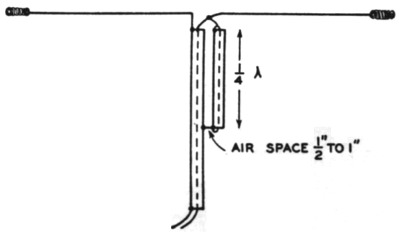
Fig. 3. The "bazooka" section sometimes used between a balanced antenna, such as a doublet, and coaxial cable to maintain antenna balance.
Other applications
Two other useful applications of quarter-wave transformer sections of transmission line are shown in Figs. 4 and 5. Fig. 4 shows a quarter-wave section or stub connected across the main transmission line. The lower end is shorted and connected to ground as a permanent protection against lightning. A quarter-wave section, or transformer, which is shorted at one end, presents a very high impedance at the other end for the frequency for which it is cut. Thus, there is little or no shunting effect on the main transmission line at or near the operating frequency, although a solid ground is provided for the system.
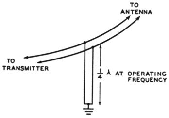
Fig. 4. Quarter-wave section for grounding a transmission line against lightning.
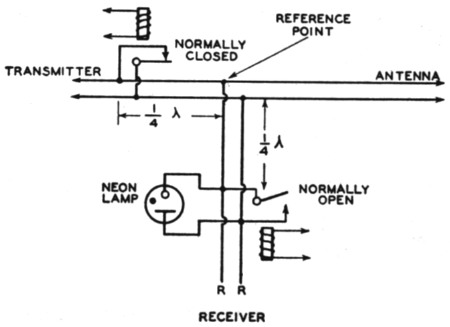
Fig. 5. A low-loss method of antenna change-over switching for the high frequencies.
Fig. 5 shows a low-loss method of transmit-receive switching which is effective for a single band. The transmitter and receiver are connected to the antenna at the same time. The arrangement may be best understood if one considers that the antenna transmission line runs continuously from the antenna to the transmitter. At a point about 3/8 wavelength out from the transmitter, the line to the receiver is tapped off. This receiver line also must be longer than ¼ wave. The tap-off point for the receiver line may now be considered as the reference point for further discussion. At a point ¼ wave from the reference point toward the transmitter, a single-pole single-throw normally-closed relay is connected. At a point ¼ wave from the reference point toward the receiver, a single-pole single-throw normally-open relay is connected across the receiver transmission line. When the transmitter is on, both relays should be energized, opening the short on the transmitter line and closing the short on the receiver line.
Since the short on the receiver line is 3 wave from the reference point, energy from the transmitter traveling toward the antenna will encounter a high impedance looking toward the receiver and very little power will be lost. The neon lamp across the receiver line at the relay is essential for protection of the receiver input in event of failure of the receiver-line shorting relay. When receiving, the signal from the antenna will pass freely to the receiver since that branch of the circuit is no longer shorted, but will lose little of its energy down the transmitter branch because that branch is now shorted 3 wave from the reference point or junction, thus presenting a high impedance to any energy which might "prefer" to be absorbed in the transmitter.
The system here described is essentially that used in radar except that special gas-discharge tubes were used in place of the relays suggested herein. This system is practical for operation at 28 Mc. and higher frequencies where the length of the quarter-wave sections is reasonable. It is particularly desirable for u.h.f. operation where the impedance discontinuities introduced by conventional change-over relays cannot be tolerated. The length of the shorting-relay leaves and connections to them must be included in the length of each quarter-wave section from the reference point.
Before connecting the receiver, careful tests should be made to check the voltage appearing across the receiver branch of the transmission line at points R and R. Connect a neon lamp across these points and observe it for glow when the transmitter is turned on. It is assumed that the relays will be energized along with application of transmitter plate power, shorting the receiver branch and opening the short across the transmitter branch. If the relays have been placed the proper distances from the reference point, there will be no glow in the lamp across the points R and R, although the neon lamp across the line at the relay may show a flash of very short duration if the relay is slow in closing. If there is no glow in the test lamp at li. and R, the test lamp may be removed and the receiver-branch line connected to the receiver input.
Considerations in construction
In constructing transformer sections of transmission line, elements may be connected in multiple to obtain lower values of characteristic impedance than may be obtained with one element. It is essential, however, to use identical material for each element. If Twin-Lead or coaxial cable is used, each element should be cut from the same length of cable. If the elements are Twin-Lead, they should be spaced apart by the spacing distance of the conductors in the Twin-Lead used. If coaxial cable elements are employed, they may be taped together.
Because the velocity of propagation (V factor) may vary slightly from lot to lot of coaxial cable or Twin-Lead, it is suggested that the transformer section be cut a few inches longer than the length called for in the formula ![]() The section may then be trimmed one-half inch at a time until the desired performance is obtained. For precise adjustment of length, an oscillator or an amplifier driven by a VFO with output at the frequency of operation may be used. The arrangement shown in Fig. 6 may be used. The quarter-wave section, cut slightly longer than the formula value, should be connected to a coupling coil and variable condenser in series as shown. The condenser must be large enough to tune the coupling coil to resonance at the operating frequency. As a first step, the condenser-coupling coil circuit must be closed by shorting directly across the end of the quarter-wave section where it connects into the pick-up circuit. The pick-up loop is then tuned to resonance with the output of the oscillator or amplifier at the desired frequency. The coupling must be sufficiently loose to minimize the detuning of the oscillator or amplifier by adjustment of the coupling-coil tuning condenser.
The section may then be trimmed one-half inch at a time until the desired performance is obtained. For precise adjustment of length, an oscillator or an amplifier driven by a VFO with output at the frequency of operation may be used. The arrangement shown in Fig. 6 may be used. The quarter-wave section, cut slightly longer than the formula value, should be connected to a coupling coil and variable condenser in series as shown. The condenser must be large enough to tune the coupling coil to resonance at the operating frequency. As a first step, the condenser-coupling coil circuit must be closed by shorting directly across the end of the quarter-wave section where it connects into the pick-up circuit. The pick-up loop is then tuned to resonance with the output of the oscillator or amplifier at the desired frequency. The coupling must be sufficiently loose to minimize the detuning of the oscillator or amplifier by adjustment of the coupling-coil tuning condenser.
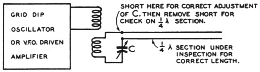
Fig. 6. Circuit for precise experimental adjustment of matching-section length.
When resonance is obtained, the short across the transformer section should be removed, again placing the pick-up coil and its tuning condenser in series across the end of the transformer section. If the grid-dip oscillator still shows a dip at the same frequency, or if the amplifier output shows maximum loading, the length of the transformer section is correct for that particular frequency. If it is necessary to tune the oscillator or the VFO to a lower frequency to obtain loading or grid dip, the transformer section is too long. The open end of the transformer may then be trimmed in small steps until the desired frequency is reached. During these operations, the variable condenser in series with the pick-up coil must not be touched. Its value, is set in the initial step, will be such as to cancel out the inductance of the pick-up loop and thereby eliminate any effect which the loop might have on the length of the transformer section.
Effects of weather
If we ignore the attenuation in a transmission line, the characteristic impedance is roughly equal to the square root of the ratio of the inductance to the capacitance of the line.
![]() where Zo is in ohms, L in henrys and C in farads. The capacitance factor is dependent upon the sizes of the conductors, their spacing, and the dielectric between them. Thus in an air- spaced line with the conductors supported on insulators, the insulators should be small in cross-section and few in number (within reason) so as to detract as little as possible from the uniform air insulation. Twin-Lead utilizes a continuous web of polyethylene as the insulator between the conductors, but in the 300-ohm type especially, the wires are widely enough separated so that the fields operate in the immediately surrounding air as well as in the polyethylene. Therefore, the dielectric constant which helps to determine the C factor and thus the Z. of the 300-ohm Twin-Lead is connected in part with polyethylene and in part with air. When the line is wet with dew condensate or rain, water joins as a third partner in establishing the dielectric constant, the C factor and the Zo. The water remains on the surface, having no effect whatever on the insulating properties of the polyethylene. But being on the surface, the water does lie in the dielectric field, and if the line is dirty there may be minor eddy-current losses within the dirt layer. The net effect of water on the 300-ohm Twin-Lead is a shift in impedance in the line itself from the impedance of the line when dry. The change in load on the transmitter will be a minimum if there are no standing waves on the line when dry. The effects of surface moisture are much less noticeable with the more closely-spaced Twin-Lead transmission lines where the polyethylene insulation is the principal dielectric.
where Zo is in ohms, L in henrys and C in farads. The capacitance factor is dependent upon the sizes of the conductors, their spacing, and the dielectric between them. Thus in an air- spaced line with the conductors supported on insulators, the insulators should be small in cross-section and few in number (within reason) so as to detract as little as possible from the uniform air insulation. Twin-Lead utilizes a continuous web of polyethylene as the insulator between the conductors, but in the 300-ohm type especially, the wires are widely enough separated so that the fields operate in the immediately surrounding air as well as in the polyethylene. Therefore, the dielectric constant which helps to determine the C factor and thus the Z. of the 300-ohm Twin-Lead is connected in part with polyethylene and in part with air. When the line is wet with dew condensate or rain, water joins as a third partner in establishing the dielectric constant, the C factor and the Zo. The water remains on the surface, having no effect whatever on the insulating properties of the polyethylene. But being on the surface, the water does lie in the dielectric field, and if the line is dirty there may be minor eddy-current losses within the dirt layer. The net effect of water on the 300-ohm Twin-Lead is a shift in impedance in the line itself from the impedance of the line when dry. The change in load on the transmitter will be a minimum if there are no standing waves on the line when dry. The effects of surface moisture are much less noticeable with the more closely-spaced Twin-Lead transmission lines where the polyethylene insulation is the principal dielectric.
We have noted before that a transmission line should be uniform throughout its length. This applies to dielectric as well as to the spacing and size of the conductors. A transmission line should not be run closer to other objects than the spacing of the conductors, and Twin-Lead, for example, should not be run in under a closed window because of its convenient form for such handling or because it seemed to work all right. Such an abrupt change in the dielectric will introduce an impedance discontinuity which may cause an appreciable power loss.
Coaxial cable, because of the confinement of fields within the outer conductor, offers the ideal solution for a permanent or semipermanent installation. It is not affected by weather nor by mounting, but it must be operated with a low standing-wave ratio to be effective.
Returning to transmission lines in general, improvement in performance is to be had in almost every case by tuning out the inductance of the coupling coil at the transmitter. Where coaxial cable is used, with the outer conductor grounded, the series tuning condenser should be connected between the center conductor and the coupling coil. With balanced feeders, such as Twin-Lead, a series condenser should be connected between each conductor of the Twin-Lead and the coupling coil. The center of the coupling coil may then be grounded.
Good antenna performance is so dependent upon proper feeder design and behavior that we are more than justified in any extra effort expanded in making the feeder system as efficient as possible.
R.M. Purinton, W9SZ.