Home - Techniek - Electronica - Radiotechniek - Radio amateur bladen - QST - Audio filters for the speech amplifier
Designing around available components.
If you have any thoughts toward speech clipping, you've got to have a good low-pass filter to back up the clipper. Here's how to design an audio filter that will meet the rather tough requirements. No previous knowledge of filters is required.
Recent issues of QST have carried a number of articles on speech clipping and filtering.(1) Whether or not clipping is used, the reason for filtering is to restrict the sidebands of a phone transmitter. The higher the audio frequency impressed on the carrier the wider the sidebands. High-frequency sidebands that are not essential to intelligibility cause unnecessary interference to neighboring channels and, since most communications-receiver i.f. amplifiers do not pass much sideband energy above about 3000 cycles, there is no reason why these useless frequencies should be transmitted. For communicating purposes audio frequencies above 2500 or 3000 cycles are not necessary for intelligible speech.(2)
Most amateurs look upon filters as being very complicated and difficult things to design and construct. The writer, knowing very little about audio-filter fundamentals, shared in this feeling - but nevertheless decided to make the attempt. Equipment was available to make measurements on experimental filters, so it was readily possible to check performance. As a result, the writer is convinced that any amateur without previous experience with filters, but having a knowledge of elementary algebra, can design and build thoroughly-satisfactory audio filters. Precision components are not necessary.
Designing the filter
There are many types of filters that could be used to do the particular job. The most common types can be classified as either a pi network or "T" network. Electrically these two types should work the same. However, in this article we will concern ourselves with the pi type because of the convenience in handling the design.Many readers are not aware that the familiar receiver power supply employs a simple pi network as a low-pass filter. A low-pass filter attenuates all frequencies above a certain frequency called the "cut-off frequency" and passes all frequencies lower than the cut-off frequency. Since we are dealing with audio frequencies that fall in the lower end of the audible spectrum, a low-pass filter would be the type suitable for attenuation of the unnecessary high frequencies, and yet pass the wanted low frequencies. After examining the various low-pass filters in Terman's Radio Engineers Handbook(3) a shunt M-derived filter was selected for simplicity and adaptability to a speech amplifier. The name itself implies fundamentals that are more advanced than will be covered, but Terman's Handbook can be consulted for the theory. It is sufficient to say here that the shunt M-derived filter, shown in Fig. 1A, not only has the cut-off frequency that is characteristic of the simple pi section but also will provide an attenuation peak at a selected frequency outside the passband.
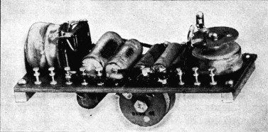
Using high-inductancc r.f. chokes and tubular paper condensers, a three-section filter is quite compact and relatively inexpensive. This one is mounted on a 2 × 6 inch terminal board.
When the filter is to be connected to the plate of an amplifier tube, it is important to keep the load or terminating resistance as high as possible. The reason for this is to obtain the largest possible signal voltage from the filter stage. With available components, the value of terminating resistance that can be used will be small compared to the optimum load for the tube, and in such a case the output voltage will be approximately proportional to the load resistance (R in Fig. 1A). The value of R depends directly on the inductance, L, in the filter. Iron-core r.f. chokes were chosen for use in the filter because of their compactness, availability and high Q as compared to larger iron-core coils. A 250 millihenry choke was the largest unit of its kind available for the experiments. The value of R can be found from the equation in Fig. 1H.
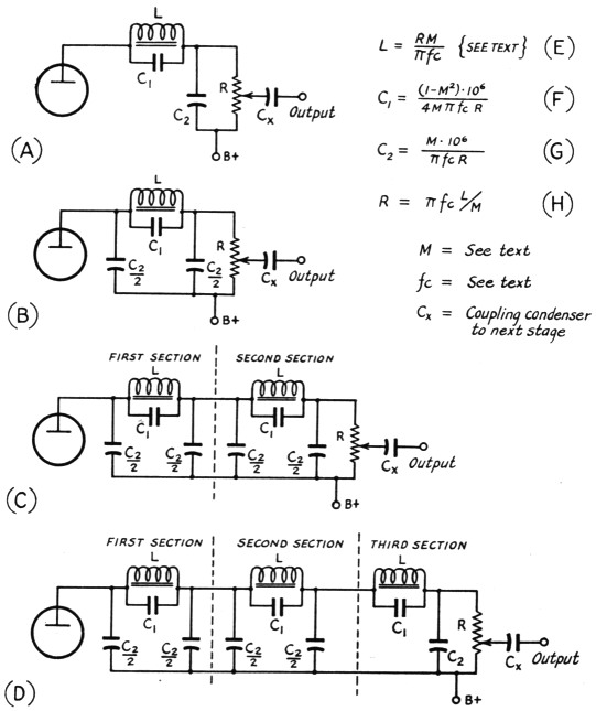
Fig. 1. Shunt M-derived filter circuits and design formulas. In the equations, inductances should be expressed in henrys, resistances in ohms, frequencies in cycles per second, and capacitances in microfarads.
Before any of the equations can be solved, M must be found from the equation
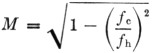
where:
fc = cut-off frequency,
fh = frequency of peak attenuation.
This brings up the problem of choosing fc and fh. The choice of fc and fn is very important inasmuch as the shape of the response curve is greatly affected by M (which depends on fc, and fh only). Although it is theoretically possible, with pure reactances, to obtain a cut-off frequency equal to the frequency of very high attenuation, practical considerations require fc and fh be not too close to each other. One reason is the impracticable size and quality in the condensers and chokes; the other reason is that the attenuation will not be very large at frequencies above the cut-off frequency if the peak attenuation frequency is close to or the same as the cut-off frequency. It has been found by experiment(3) that if the value of M is equal to approximately 0.6, the filter will have comparatively-flat response characteristics in the passband (voice range) and will still attenuate effectively the unnecessary high frequencies. Very elaborate filters can be designed to give better response characteristics than the shunt M-derived, but they are not necessary for practical purposes.
It is sometimes quite necessary to connect sections of filters together as shown in Figs. 1C and 1D for greater attenuation of high frequencies, without affecting the passband. As long as sections of the shunt M-derived filter are designed for the same load resistance, they can be connected in cascade as shown in Fig. 1D. Only one terminating resistance is necessary for the complete filter. If fc is kept constant, a different value of fh may be assigned to the various sections without affecting the terminating resistance. This practice will give more uniform suppression at all frequencies above cut-off than is possible with a series of sections each having the same fh. However, if f. needs to be changed for different sections to hold M near 0.6, L must also be changed to keep R at the same value for all sections.
Losses in the filter itself are mostly attributable to the a.c. resistance of the coils. With the r.f. coils mentioned they are small and need not be considered in design.
The number of sections to be used in the filter will depend on the amount of attenuation needed. The total attenuation of the filter is the sum of the attenuations in all sections. A one-section shunt M-derived filter is shown in Figs. 1A and 1B. Either circuit may be used since the two are electrically equivalent. In general, at least two sections, as shown in Fig. 1C, should be used, and a third section may be added, as shown in Fig. 1D, to give very high attenuation at all frequencies outside the passband. Each section is designed separately, and they are then joined together to form the complete filter as shown in Fig. 1D.
| Section | C1 (µF) | C2 (µF) | R (Ω) | L (Henrys) | M Computed | fc Cycles | fh Cycles | |||
|---|---|---|---|---|---|---|---|---|---|---|
| Ideal* | Actual | Ideal | Actual | Ideal | Actual | |||||
| First | 0.0063 | 0.006 | 0.0199 | 0.02 | 3550 | 4000 | 0.25 (given) | 0.665 | 3000 | 4000 |
| Second | 0.0063 | 0.006 | 0.0199 | 0.02 | 3550 | 4000 | 0.25 (given) | 0.665 | 3000 | 4000 |
| Third | 0.0033 | 0.003 | 0.0125 | 0.015 | 3550 | 4000 | **Computed 0.157 H but used 0.20 H (Millen 34400-200) | 0.696 | 5000** | 7000 |
*For M = 0.6.
**Cut-off frequency changed from 3000 to 5000 cycles.
Practical filters
A one-section filter, as shown in Fig. 1B, was tried first. Since L was previously decided upon as a 250 millihenry choke (Millen 34400-250), R was determined from the equation shown in Fig. 1H. Bearing in mind the considerations discussed earlier, fc and fh were chosen as 3000 and 4000 cycles, respectively. After solving for M, using these values for fc and fh, the rest of the components were determined easily by direct substitution in the formulas shown in Fig. 1.
The closest stock values were used in making measurements for the response curve shown in Fig. 2. Table 1 shows the ideal values of components compared with values actually used.
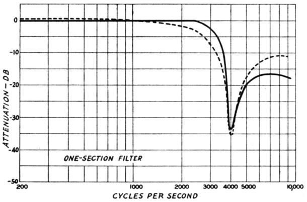
Fig. 2. Measured attenuation characteristic of a single-section filter (Fig. 1B) using the constants given in Table 1. Reference level (0 dB) is the output level at 1000 cycles. The solid curve is the response with the source of signal having an internal impedance of 7500 ohms, simulating the plate resistance of a medium-µ triode. Dashed curve is the response measured with a 500-ohm signal source.
The curves resulting from use of high-and low-impedance signal sources are shown in Fig. 2. The 50 dB line represents the hum level of the better-thanaverage high-gain speech amplifier. It will be noted that with a one-section filter insufficient attenuation was achieved. Enough signal at high frequencies was passed with the gain open full to override the hum level of the amplifier.
It was then decided to add another section to the filter as shown in Fig. 1e. The same choice of fc and fh was used so that the components were the same as the first section. The output condenser of the first section and the input condenser of the second section can be lumped together to form one condenser. Values computed and values actually used are listed in Table 1. The curve shown in Fig. 3 is the result of experi ments with a two-section filter. Note the large attenuation at approximately the frequency of peak attenuation. Some high-frequency signal above 4500 cycles was passed, but for most practical purposes this amount of attenuation would do a satisfactory job of cutting sidebands.
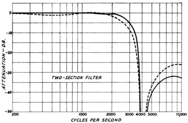
Fig. 3. Attenuation characteristic of a two-section filter (Fig. 1C) using constants given in Table 1. Measurement conditions same as in Fig. 2.
A third section was added to the filter as shown in Fig. 1D to see if the high end could really be attenuated. Since the two-section curve began to level off at 7000 cycles, this frequency was chosen as fh for the third section. In order to keep M at approximately 0.6 and R constant for all sections, 5000 cycles was chosen as fc. The values used and the ideal values are listed in Table 1. The curve shown in Fig. 4 represents the results with a three-section filter. It will be noted in Fig. 1D that a section similar to Fig. 1A was used instead of the type shown in Fig. 1B. There should be no difference in results since both are electrically the same. The results were excellent. Attenuation was high enough to suppress all frequencies above 4025 cycles to a level far below the hum of the amplifier.
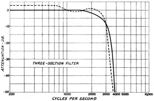
Fig. 4. Attenuation characteristic of a three-section filter (Fig. 1D) using constants given in Table 1. Measurement conditions same as in Fig. 2.
Some Suggestions
Increasing the capacitance of the output condenser of the last filter section will increase the attenuation at the higher frequencies outside the passband without greatly affecting the shape of the curve inside the passband. Two or three times the theoretically-correct capacitance can be used. In the case of a two-section filter having the curve shown in Fig. 3, for example, the output capacitance is 0.01 µF. (C2/2). Increasing the capacitance to 0.02 or 0.03 µF. will increase the attenuation above 4500 cycles. It also will have the effect of making the cut-off less sharp; this is not at all a disadvantage, because a very sharp cut-off tends to cause transients that introduce a sort of "ringing" on voice peaks.
The entire filter unit can be constructed on a standard 2 inch-wide mounting board, its length depending on the number of sections used. Care should be taken to mount the iron-core chokes at right angles to each other, to minimize coupling that might affect the characteristics of the filter. The photograph shows a three-section unit constructed in this fashion. (This particular filter is not the one whose performance is shown by the curves of Fig. 4, but is similar in circuit. It was designed to use the 125 millihenry r.f. chokes commonly available, and for this reason a lower value of terminating resistance - 2000 ohms - is required. Also, the cut-off frequency in this unit was set at 2500 cycles rather than 3000, giving even smaller effective channel width without affecting intelligibility. Its out-of-band attenuation is of the same order as with the unit shown in Fig. 4.)
When the high-frequency cut-off is in the vicinity of 3000 cycles, the naturalness of speech may be somewhat improved by attenuating at the low-frequency end below 200 cycles. This can easily be done by reducing the capacitance of interstage coupling condensers in the amplifier to about 0.005 µF.
Insert the filter in the plate circuit of a speech-amplifier stage where the level is fairly high - at least several volts. This will decrease the possibility of hum pickup and will attenuate any harmonics, above the cut-off frequency, that may be generated in the preceding low-level stages. An extra stage of audio will be needed to compensate for the low gain in the filter stage. One half of a twin triode such as a 6SN7GT can be used to build up the gain while the other half incorporates the filter.
The d.c. plate voltage for the tube should be applied through the filter, as indicated in Fig. 1. This allows the use of a coupling condenser of normal capacitance between the filter and the grid resistor of the next stage. A wire-wound potentiometer can be used for the load resistance, R. The output of the filter stage can then be conveniently adjusted byeithera knob or screwdriver.
If the expected results are to be obtained from the transmitter after installation of the filter, it is very important that the audio stages following the filter be free from distortion. The modulated r.f. amplifier also must be functioning properly, since the filter cannot cure a broad signal caused by nonlinear operation or overmodulation. Only through conscientous attention to these critical factors will amateurs realize maxium utility from the crowded phone assignments.
Notes
- W. W. Smith, "Premodulation speech clipping and filtering," QST, February, 1946;
"More on speech clipping," QST, March, 1947.
Also J. W. Smith and N. H. Hale, "Let's not overmodulate - It isn't necessary!", QST, November, 1946. - Grammer, "House cleaning the low-frequency phone bands," QST, May, 1947.
- F. E. Terman, Radio Engineers Handbook, McGraw-Hill Book Company, New York.
Julius L. Galin, W1LOP.