Home - Techniek - Electronica - Radiotechniek - Radio amateur bladen - QST - Better N.F.M. reception with A.M. receivers
A simple narrow-band F.M. adapter.
Reception of narrow-band f.m. or p.m. signals by detuning the receiver is at best a makeshift that does not bring out the full possibilities of the system. Ilere are two simple adapter circuits that will give true f.m. reception with an ordinary a.m. superhet. The receiver can he changed instantly from f.m. to a.m.
Much has been said and written in the last decade about narrow-band f.m., and there is currently much controversy regarding the merits of a.m. and f.m. However, the purpose of this article is not to engage in such controversy, but to describe a practical, inexpensive adapter unit for a.m. receivers. As is well known, the use of n.f.m. usually will allow those otherwise in the doghouse because of BCI to operate during the evening hours. Likewise, it offers an inexpensive means for the c.w. man to try his hand at phone operation.
Quite a few hams are now using n.f.m. transmission, but most of the receivers in current use are of the straight a.m. type. It is our experience that f.m. reception on a receiver equipped with an f.m. adapter is quite an improvement, from the standpoint of readability, over the same signal received by detuning the a.m. receiver to detect the f.m. signal on the i.f. slope.
The following description of an n.f.m. adapter does not differ radically from one described some years ago in QST,(1) and most of the points brought out in that article are applicable to this unit. While we do not flatter ourselves that this is the ultimate in the design of a good f.m. adapter, the simplicity of the unit lends itself to ease of construction and it is possible to use this as the basic unit to which various circuits can be added in experimenting further with n.f.m. Our desire was to hold the basic unit to two tubes in order to minimize the drain on the "A" and "B" supply of the receiver with which it is used. If a separate filament supply is used, more stages can be added as desired. Of course, much depends on the receiver to which this adapter is attached, insofar as the results to be achieved are concerned. The receiver should have ample gain to give good limiting action on weak signals.
It has been our observation that when the receiver gain is sufficient, the background noise will rise sharply on each side of the f.m. carrier, and will mask three-spot tuning effects which may otherwise be noticed because of discrimination by i.f. selectivity-curve sides. The adapter has been used with both the HRO and NC-173 receivers with satisfactory results. With the adapter in use the "on-signal" noise level from external noise is reduced because of limiter action, and reports from noisy locations indicate that an improvement in readability is immediately noticed when receiving f.m. signals. Since the adapter allows you to tune to the center of the incoming carrier, any a.v.c. action in the receiver can be used to advantage to hold the "on-signal" noise level down by reducing receiver gain, an advantage that cannot be realized with i.f. slope detection. "Off-signal" noise is somewhat greater than with a.m., but this is not too serious since most tuning is done on a.m. and the adapter is switched in when an f.m. signal is present. Later in the article we will describe how a slight addition can be made to reduce the noise level to a value comparable with a.m.
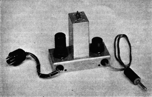
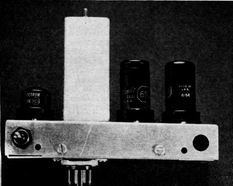
This two-tube adapter gives n.f.m. reception with a communications receiver having an i.f. in the vicinity of 456 kc. The tubes are a 6SJ7 and a 6H6.The phone plug, connected to the audio output terminal in the unit, is plugged into the phono jack on the receiver for f.m. reception, and simply nulled out of the jack for a.m.
Adapter Circuit
Basically, the adapter unit consists of a limiter stage followed by a discriminator. The limiter uses a 6SJ7 tube with a 10-A ad. coupling condenser and a 1 megohm grid leak, as shown in Fig. 1. The tube will reach full limiting at about 2.5 microvolts input to the NC-173 receiver, and the limiter output is constant over a wide range. In tests made with a.v.c. off, the receiver i.f. system overloaded before it was possible to overload the limiter, indicating that little would be gained from the standpoint of maintaining constant output by adding another limiter stage. A graph of limiter action is shown in Fig. 3.
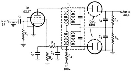
Fig. 1. The n.f.m.-adapter circuit.
| C1 | 10 pF ceramic or mica. |
| C2,C3 | 0.1 µF paper. |
| C4,C5 | 100 pF ceramic or mica. |
| R1 | 1 MΩ, watt. |
| R2,R3 | 33 kΩ, 1 watt. |
| R4,R4,R6 | 100 kΩ, ½ watt. |
| T1 | Discriminator transformer (National SA-4842). |
The discriminator transformer used is an experimental one consisting of two separate low-impedance primary windings, each with a separate secondary winding coupled to it. Each half of the transformer secondary is fixed-tuned with a 510 pF silvered-mica condenser, and variable tuning is accomplished by means of movable iron cores. One of the transformer secondaries is tuned to a frequency approximately 10 kc. higher than the i.f. of the receiver to which it is attached. The other is tuned approximately 10 kc. lower than the i.f. The transformer should be used with a receiver having an i.f. of approximately 456 kc. The bandwidth of the transformer is approximately 20 kc. and the characteristic is quite linear over approximately 12 kc. The output of the discriminator is fed directly to the receiver audio system. Discriminator output is approximately % volt per kilocycle of frequency deviation, as shown in Fig. 2.
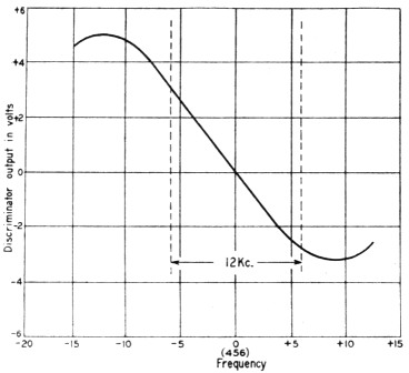
Fig. 2. Discriminator operating characteristic.
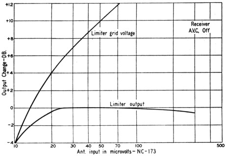
Fig. 3 - Limiter operating characteristic.
Construction of the unit is relatively simple, as will be apparent from reference to the photographs and schematics. It is possible to construct it in an evening; in fact, several have been made at the one-per-man-per-evening rate. The chassis, which measures 2¼ × 5 × 1 inches, is constructed from a piece of 0.062 inch aluminum sheet measuring 4¼ × 7 inches. Construction can be simplified by using a piece of metal 4¼ by 5 inches and by putting only two bends in the chassis, making it "U" shaped. Socket holes, as well as the mounting holes for the discriminator transformer, are punched before the chassis is bent to its final shape. Insulated lugs can be mounted on socket screws, as shown, to provide for neat layout of parts.
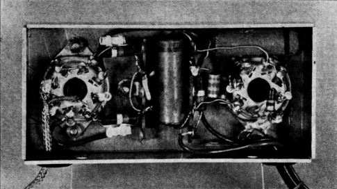
The simplicity of the wiring is evident in this underneath view of the adapter. The i.f. lead, a piece of small coaxial cable, is laced with the power and audio leads.
Most NC-173 receivers are provided with adapter sockets at the rear into which the adapter may be plugged. This adapter socket provides all voltages necessary to operate the adapter, as well as i.f.-output and audio-input connections; thus no other connections need be made to the receiver. In the first experimental model of this adapter, the audio output was run through a shielded lead to the phonograph-input jack on the front of the receiver, and switching from a.m. to f.m. reception was accomplished by inserting the plug in the phono jack. Simpler methods can be devised, especially if the user has no objection to adding a switch to the front panel of his receiver. In this event it is simply necessary to switch either the a.m.-detector output or the f.m.-discriminator output to the audio input of the receiver. It is not necessary to switch off the B-plus of the adapter tubes since interference from crosstalk is negligible.
On the NC-173 receiver, i.f. output is taken from the plate of an a.v.c. amplifier tube so that any detuning effects caused by the unit are not noticeable in the normal operation of the receiver. However, when the adapter is used with other types of receivers, the output must be taken from the plate of the second i.f. tube, and there will be some detuning of the detector input transformer. The simplest way to retune the detector transformer, when no signal generator is available, is to set the receiver for maximum background noise with no signal present. When this unit is used in connection with receivers having high-impedance i.f. systems, care must be taken to have the lead from the i.f. tube to the limiter well shielded and as short as possible. Small coaxial cable, such as RG-59/U, should be used for this lead. In the event oscillation troubles are encountered in the receiver with the adapter in place, make sure the adapter unit is well grounded to the receiver and all shielding is attached to a good ground, preferably in the receiver if possible.(2)
This model incorporates a squelch tube to reduce interstation noise. It is also constructed so that can plug directly into the socket on the receiver. The switch at the left (not shown on the circuit diagram) replaces the plug-and-jack system used in the two-tube model as an audio changeover from f.m. to a.m.
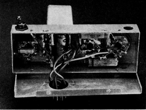
Wiring of the three-tube unit is practically as simple as in the two-tube adapter.
Alignment
After the narrow-band f.m. adapter has been attached to the receiver and the receiver properly retuned, if necessary, to compensate for any loading effects, the following procedure can be used to align the discriminator transformer by ear:
With one of the trimmers well detuned (slug all the way out), tune the other trimmer for maximum background noise. Needless to say, this adjustment should be made on a clear channel. Any front-end frequency will do. With the slug tuned for maximum background noise, tune the other slug for a null. Both circuits are now tuned to center frequency. Turn one slug in (clockwise) 1½ turns and the other one out (counterclockwise) 1½ turns. This puts one tuned circuit higher in frequency than the center frequency and the other one lower. The trimmers can now be adjusted for best response on some local f.m. signal.
The above method is the easiest way 10 tuning up the discriminator transformer. However, it is by no means the most accurate, although satisfactory results can be obtained. If a signal generator and a high-resistance voltmeter are available the process can be made much more accurate, and the following liprocedure is recommended:
Connect the voltmeter across one of the diode load resistors, as shown in Fig. 4, and time the circuit associated with that diode for maximum reading on a strong signal that is detuned about 10 kc. If no signal generator is available, a strong local broadcast station can be substituted. Now connect the meter across the two diode resistors and, with the receiver tuned to resonance with the incoming carrier, tune the other circuit for zero reading. It is a good idea to start this adjustment with one slug all the way in and the other all the way out, to avoid tuning both circuits to the same frequency. As the curve in Fig. 2 shows, the peaks of the discriminator characteristic will be approximately 10 kc. each side of center frequency. The discriminator will be linear over about 12 kc., which exceeds the i.f. passband of most communications receivers.
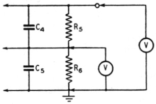
Fig. 4 - Voltmeter connections for aligning discriminator. A high-resistance (20,000 ohms or more) voltmeter must be used.
F.M. reception
The following observations will give some insight as to the type of performance to be expected. When the receiver is switched from a.m. to f.m. with no signal present, a considerable amount of tube noise will be heard and it will probably be necessary to reduce the audio gain. This is also true when listening to an f.m. signal when the carrier is suddenly switched off. However, we have found that this apparent defect is not too objectionable, and it can be circumvented in several ways. If the signals are tuned with the receiver set for a.m. reception and switched to f.m. only when an f.m. signal is present, most of the trouble from this source will be eliminated. Also, an additional tube can be incorporated, as described later, to quiet the receiver when f.m. signals are not present.
The use of the S-meter is particularly desirable when tuning to an f.m. signal because it is important to tune to the exact center of the incoming f.m. carrier. If the signal is tuned off center, considerable distortion may be caused by working on one side of the i.f. selectivity curve of the receiver. If no S-meter is handy, a little practice in tuning through f.m. carriers will aid the operator in determining when the proper center operating point has been reached.
It is possible to secure very effective limiting on f.m. signals without the distortion that usually accompanies severe limiting of a.m. signals. In noisy locations it has been observed that with the adapter f.m. signals are much improved and generally more enjoyable to listen to when heavy ignition noise is present. This is also true when there is heavy interference, because it is possible to tune to the center frequency of the incoming f.m. signal and avoid the off-center tuning necessary with i.f.-slope detection. The improvement in signal strength is generally in the order of 6 db. or better, and this can be the difference between a readable f.m. signal and one that is lost in the general background noise and QRM.
When receiving strong and weak f.m. signals simultaneously it will be found that the strong signals mask the weak ones when the two carriers are very close. However, there is very little heterodyning, and the received carrier is generally much more intelligible than would be the situation with two a.m. signals of comparable strength.
At times it may be found that an incoming f.m. signal is badly distorted. This is not attributable to the characteristic of the discriminator transformer, but to the selectivity curve of the receiver. Any incoming signal that deviates beyond the selectivity curve of the receiver will be distorted, and the adapter should not be blamed for this distortion because it originates in the receiver i.f. The remedy is to have the operator of the f.m. transmitter reduce his speech gain and thereby reduce the frequency deviation, thus conforming to FCC regulations.
Squelch circuit
As an improvement in the original narrow-baud f.m. adapter, the circuit shown in Fig. 5 was developed to eliminate some of the "off-signal" noise when the f.m. adapter is in use. This circuit simply adds another tube as a squelch. A 6J5 tube is used with its grid in parallel with the 6SJ7. It is necessary to change the value of R3 and to eliminate R: to provide proper operating voltages for the added tube. R7 and C6 form a filter circuit so that only direct current is applied to the 6J5 grid.
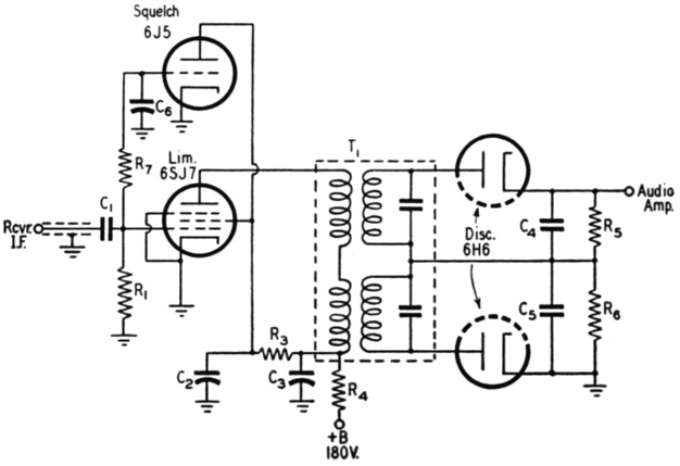
Fig. 5. Circuit of the n.f.m. adapter with squelch tube. Values are the same as in Fig. 1 with the following exceptions:
C6 0.1. µF paper.
R3 2.2 megohms, 1 watt.
R7 1 megohm, ½ watt.
In operation, with no signal present the 6J5 plate draws current and drops the voltage on the 6SJ7 screen to a point where limiting occurs down in the actual noise of the receiver, thereby eliminating much of the noise formerly present. However, when a signal is present rectification in the 6SJ7 limiter grid circuit develops a negative voltage across R1 that cuts off the 6J5 and allows the voltage on the 6SJ7 screen grid to rise to a point where the limiting is adequate for the incoming signal. Since the 6J5 draws no current, once cut off by the incoming signal, the limiter screen voltage and, therefore, the limiter characteristic remain constant over a wide range of input sig nais. The addition of this tube adds little to the B+ drain on the receiver. However, because of the added filament current it is advisable to ascertain that the receiver with which the adapter is to be used is capable of withstanding the additional drain before adding the squelch tube. Alternatively, a separate filament transformer can be used.
In practice, at W1JEL it has been found that speech clipping can be used to advantage in the f.m. transmitter. Speech clipping tends to give the impression, at the receiver end, that an excessive amount of deviation is being used, although the signal is clear and lacks any trace of distortion caused by exceeding the i.f. bandwidth of the receiver. Undoubtedly similar methods can be used to advantage in n.f.m. transmission.
No doubt many refinements and alternatives could be used to advantage with this narrow-band f.m. adapter; it is possible that cascade limiters, ratio-type discriminator transformers, germanium crystals and similar devices will lead to even more compact, if not more effective, units. However, we feel that the need for a simple and inexpensive narrow-band f.m. adapter is the urgent thing at the present time. It is hoped that more hams will give f.m. a break by building similar units.
Notes
- Grammer, "Some thoughts on amateur f.m. reception," QST, March, 1941.
- It is readily possible, of course, to use the socket idea on other receivers, provided there is a convenient place for it near the last i.f. transformer. The socket results in a more clean-cut lob than a collection of leads tied in at various points in the receiver and brought out saparately to the adapter.
Edmund Harrington, W1JEL
William Bartell, W1PIJ.