Home - Techniek - Electronica - Radiotechniek - Radio amateur bladen - QST - Combination bias supply and control system
The circuit shown in Fig. 1 makes use of several 24 volt d.c.-operated relays and a transformerless bias supply in an arrangement suitable for use with a low-power transmitter that uses 6L6s or 807s in the final amplifier. The relays are currently available at small cost in the surplus market.
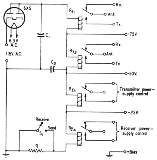
Fig. 1. A novel method of using surplus low-voltage relays in a bias and control circuit for the low-power rig.
C1,C2 20 µF 150-volt electrolytic.
R 2500 ohms, 10 watts.
Ry1,Ry2,Ry3,Ry4 - See text.
S1 S.p.s.t. toggle switch.
As shown in the diagram, the coils of the relays are connected in series, and are used as a tapped bleeder across the bias supply. A 2500 ohm resistor is used to reduce the current through the coils to a point below that required for them to throw. A toggle switch shorts this resistance, causing the relays to throw tolurn the transmitter on. The voltage drop across each relay coil may be used as a source of bias voltage in cases where the grid-current requirements of the transmitter are low. The voltages indicated in the diagram are typical of those obtained. When the switch is thrown to the receive position, the bias voltage increases above these figures, because the drain on the rectifier is then reduced.
Since the relay coils are connected in serie, damage to the transmitter in case of bias failure is prevented, as the relays will not close. Similarly, if the coil of one relay opens, power cannot be applied to one part of the transmitter while it is not applied to another.
With the transformerless supply shown, a polarized a.c. plug must be used. There is no reason why the series-connected relay idea cannot be used with the standard transformer-type supply, however.
Rod Grant, W1MDS/6.