Home - Techniek - Electronica - Radiotechniek - Radio amateur bladen - QST - The "Q5-er"
An outrigger amplifier for real i.f. selectivity.
This article is not recommended to readers who never have any trouble copying phone signals during the peak operating hours in our phone bands, because the "Q5-er" can do them no good. It isn't even going to be much help to the "high-fidelity" merchant who insists on everything being flat out to 15,000 cycles. But if you would like to find out how to squeeze a few solid QSOs out of the band under "impossible" conditions, you will get plenty from the experiences W1DBM has had with his sharp i.f. amplifier. It can be attached to any receiver with only a few changes.
The other night, during a QSO on 75, the chap at the other end mentioned that his new receiver was so hot on 75, and all stations came in so strong, that at times he wished it had less sensitivity so that he could separate stations better. That remark made up our mind then and there to write this little epistle. "How long," we asked him, "has the sensitivity of a receiver had anything to do with the selectivity?" They are two different animals. We told him that what he wanted was not less sensitivity, but rather more selectivity. And that's what all receivers need today.
There have been many "preselectors" described in QST and other radio magazines, covering all sorts of gadgets from one-tube jobs to six-tube converters that are really complete new front ends for the ham receiver. However, there has been only one device described in recent years to make signals more readable, and that appeared in October QST.(1) It doesn't do much good to boost a signal 30 dB to an S9 unless it is Q5.(2)
A modern superhet receiver consists of three essential parts: the r.f. stage or stages, the i.f. stage or stages, and the audio. Of course, detectors, oscillators and power supply are necessary, but the gain and selectivity are obtained in the three sections just mentioned. The r.f. section has to be tunable so that it will amplify the desired station but, equally important, it must have sufficient selectivity to reject the image frequency. This means at least two stages, not one, of r.f. ahead of the first detector. Also, the first stage must be well designed, since it controls the over-all signal-to-noise ratio of the whole set. Only the four top-priced receivers meet this requirement. If you don't believe this, visit almost any amateur station and see the assortment of preselectors and converters being used to "pep up" what they thought was the latest word in receivers when they bought it. These same operators will rave about the improved signal-to-noise ratio, the lack of images, and will tell you they can now hear weak signals that were entirely missing on the receiver without the pre-selector or converter. This is definite proof of the need for a better front end in practically all of the usual run of amateur communication receivers. About now we can hear the reader saying "So what? I know all that, it's old stuff, and besides I have a red-hot converter and a couple of R9-ers." Well, that's the reaction we wanted, because it leaves the reader wide open when we reply, "O.K. So the signal is 89. But is it Q5? How about the second essential part of your receiver - what have you added to it?"
This second essential part of a superheterodyne, the i.f. amplifier, has the sole purpose of providing for the receiver sufficient gain and selectivity without adding a lot of ganged tuning controls. In other words, the i.f. amplifier is the part of your receiver that determines whether or not you can copy a given station in severe QRM. Many receivers only have one stage of 465 kc. i.f. amplification and get plenty of gain but no selectivity to speak of. Therefore, the use of more than one stage is to provide additional selectivity. It is a well-known fact that almost anyone can build a two-stage i.f. amplifier without any difficulty, but feed-back and oscillation troubles often start when three are attempted. At least one well-known high-priced receiver uses three i.f. stages for some added selectivity, but why stop there before the required amount has been reached? If more than two or three stages of i.f. give trouble on 465 kc., there is no law against converting this to a new lower i.f. of from 50 to 200 kc. and having several more stages.
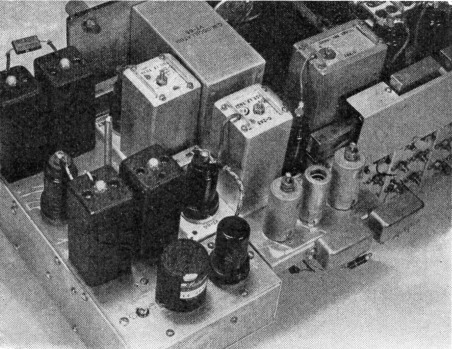
A rear view of the "Q5-er" mounted on a BC-312 receiver. The 6C5 in the foreground is the oscillator that feeds the 6K7 mixer on the BC-312 chassis (note the second shielded lead up to the 6K7 grid cap). The oscillator-coil can and tuning-condenser shaft are to the left of the 6C5. The next two square cans are the first pair of 175 kc. i.f. transformers, followed by the 6K7 amplifier and the gain-control shaft and then the second pair of i.f. transformers. A partition under the chassis divides the oscillator and i.f. portions and, combined with a bottom plate, effectively prevents oscillator radiation. The small extra chassis to the right of the "Q5-er" is the outrigger "booster" amplifier.
This brings us to the reason for this article, namely, the inexcusable lack of selectivity that modern receivers have. The only reason we went to superheterodynes in the first place was to get higher selectivity. Today, with twice as many stations on the air, and the QRM more than twice as bad, what is the bandwidth of the new 1947 receivers? Just about the same as in 1935. And what is the usual excuse given? "Amateurs like to have nice quality so they can listen to the broadcast band." We say "Aw, nuts!" Right now, as we write, we are listening to a symphony over WQXR. Our receiver with a "Q5-er" is sharpened almost to the point of single-sideband reception, and the music sounds a lot better than it does on most of the small portables with which thousands of BCLs are satisfied.
At the present writing (set manufacturers take notice) there is not a single communication receiver on the market at any price that will cope with the QRM, because they are all designed to give almost broadcast-quality reception. True, most of the better ones have a crystal filter which helps a lot, but it is not the answer.
A crystal filter properly designed (and many of them are not), in a receiver that is properly aligned to the crystal frequency, will do a very good job. However, the tuning is critical, the phasing is tricky, and at best it will only take out one heterodyne at a time while keeping you as busy as a one-armed paperhanger trying to hold the thing in tune. It has a bell-like tone when shocked by noise impulses and key clicks, and sounds hollow when slightly off tune. As pointed out by McLaughlin,(1) the heterodyne structure gets very complicated, and when three signals beat with the desired signal they produce six heterodynes (this is a mild form of QRM). General hash and sideband splatter are even more complicated when they have several adjacent carriers to beat against. A simple answer to the problem, therefore, seems to be an i.f. amplifier that is really selective, like the "Q5-er" - not 6 or 8 kc. wide at two times down, but only 1.5 kc. wide at two times down, 4 kc. wide at 10 times down, 6 kc. at 100 times down, and only 7.5 kc. at 1000 times down, combined with a variable-selectivity crystal filter. Yes, the crystal filter really works when you have a good i.f. to back it up. No matter what make of receiver you now have, you can make a very decided improvement in reception by adding a "Q5-er."
Greafer i.f. selectivity
The design of this "Q5-er" started after the purchase of a BC-312-M and a BC-348-R, when it was discovered that, in the daytime, they would both pull in weak stations on 75-meter 'phone that the old reliable communication receiver could not even find in the noise. Yet in the evening, when QRM got bad, they were both more or less useless. It was decided to try to do something about it. The first step was to acquire a surplus crystal-filter unit from a BC-342 and install it in the 312. This helped but was obviously not the answer. After studying the circuit diagram, a loading resistor was noticed across one of the i.f. transformers, apparently to increase the bandwidth. It was decided to eliminate this resistor, and so the transformer was removed from the chassis and taken apart. After taking the shield can off and removing the resistor, it seemed like a good idea to space the windings farther apart, as they seemed to be overcoupled. This was done. The BC-312-M had noticeably better selectivity now, so the remainder of the i.f. transformers were taken apart and their windings were also spaced farther apart. To do this it was necessary to melt off the wax with an infrared lamp and slide the windings apart, so that the tuning slugs now tune from the inside out instead of from the outside in. After this was completed, the receiver was slightly better. However, the over-all gain was now reduced so that the audio had to be run pretty well up on most stations. The next step was to add a third stage of i.f., to bring back the gain. We did not need much gain, however, so it was thought that if we used two extra transformers for more selectivity and one Type 9003 miniature tube the whole works could be put on a little strip on the rear of the chassis. After this addition the gain was right back where it should be and the selectivity was still better. The old "312" could now be used at night on both 75- and 20-meter 'phone. Its measured selectivity was now better than that of a well-known expensive communication receiver.
The receiver was used for several weeks when suddenly the idea hit us that, if such a big improvement could be made so easily, possibly still more improvement could be made. Although no trouble had been encountered with oscillation, it was considered inadvisable to add more stages at 470 kc. Therefore the last i.f. tube was made into a converter to 175 kc., and the output was fed over to a new chassis. This new chassis contained the 175 kc. i.f. transformers and a 6K7. The last transformer was so placed that it could feed right back into the second detector of the "312." Ten minutes after the last wire was soldered in place we were listening to the 75-meter 'phone band, and it was an entirely new and different experience. The improvement is so great that you can tune in the same station on two receivers, one with and one without a "Q5-er," and when the QRM makes it impossible to copy the station on the receiver without the "Q5-er," you can switch to the other receiver and copy the station 100 per cent, relatively free from heterodynes and sideband splatter!
It is even possible to tune in either the high or low sideband (you only need to listen to one - they are both saying the same thing!) and of course you pick the one that has the least QRM. If you are listening to a station that is relatively in the clear and a bad heterodyne appears, it can usually be eliminated simply by tuning to the other sideband.
There are two reasons for using a lower frequency. First, more tuned circuits are needed. and regeneration and oscillation may result if they are added to the present i.f. Secondly, more selectivity can be obtained at the lower frequency. We selected 175 kc. because reasonably good transformers are available on the surplus market or in various bargain basements. Aside from the i.f. transformers, no special parts are needed that won't be found in the average junk box, except possibly the oscillator coil. The one used here was a small shielded replacement b.c. oscillator coil that is fixed-tuned to around 640 kc., depending on your present i.f. The correct frequency is found by adding 175 to your present i.f. For example: 175 plus 465 equals 640.
The practical circuit
Referring to the circuit diagram of the "Q5-er" in Fig. 1, you will note that two i.f. transformers have been used between stages instead of one, and in this way eight tuned circuits at 175 kc. have been added. You will also see that in this particular case the output of the "Q5-er" is fed right back into the receiver, and the original second detector is used as the new third detector. This is not at all necessary and, in the case of certain receivers, it might be more desirable to build a third detector complete with a good noise limiter, b.f.o., a better a.v.c. system, and a vacuum-tube S-meter, and only feed the audio back to the receiver. A squelch circuit could also be added. We already have such a chassis under construction.
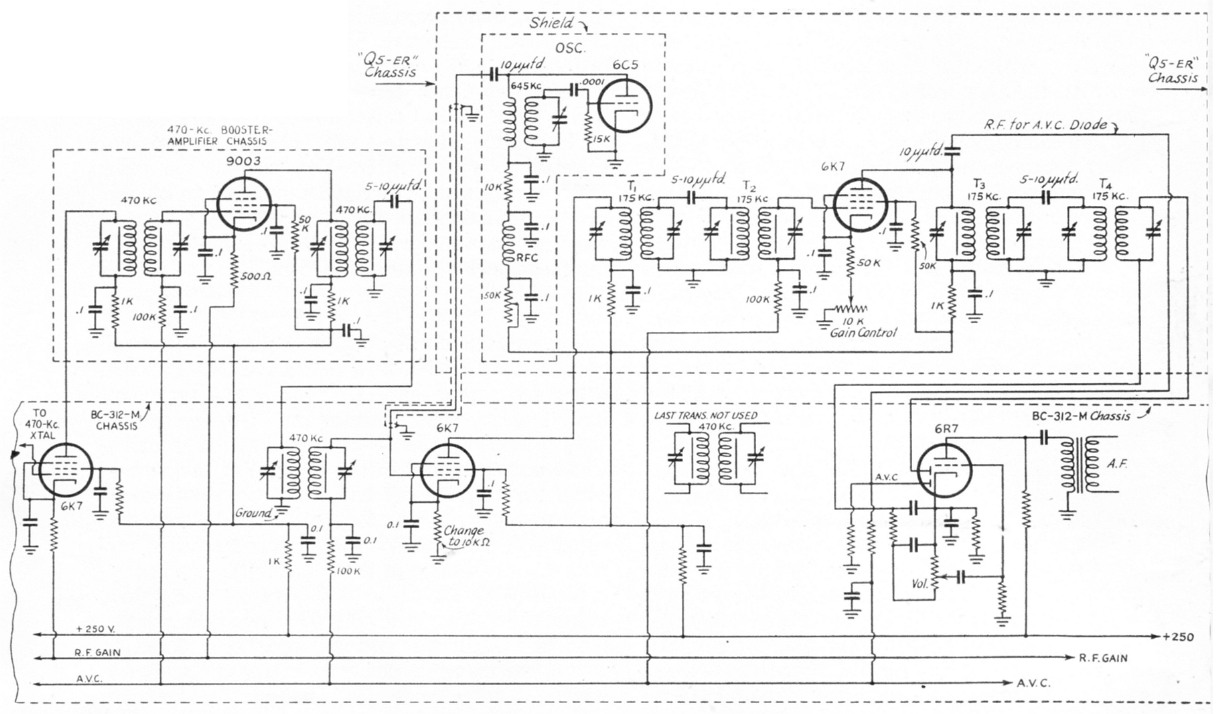
Fig. 1. The circuit diagram of the "Q5-er" as added to the BC-312 at W1DBM.(3) The 470 kc. booster amplifier is also shown, but it probably isn't necessary if the "Q5-er" is used. The decoupling already in the BC-312 is used wherever possible.
T1,T4 - 175 kc. air-core transformer (Meissner 16-5702);
T2 - 175 kc. iron-core transformer (Meissner 16-5728);
T3 - 175 kc. iron-core transformer (Meissner 16-5730).
It should be mentioned that it will be necessary to change over the b.f.o. in the receiver to the new i.f. of 175 kc. No trouble of any sort was encountered in getting this "Q5-er" to perk right off the bat. It was far easier to build and wire than any preselector or converter, because lead length and placement of parts are far less critical at these low frequencies. The only part that should be well filtered and shielded is the 640-kc. oscillator. Also it should be run at as low a plate voltage as possible, consistent with good conversion, so that it will not scatter harmonics in the amateur bands. No trouble of this sort has been encountered so far, although we did take the precaution of shielding the entire oscillator section.
The coupling between each of the i.f. transformers is a small mica condenser of 5 to 10 pF. This is about what you will get by twisting the leads together for an inch, and it works just as well. If you use more capacity you will get more gain but less selectivity. The unit as described has a gain of very slightly more than one. The gain of the tube just about makes up what is lost by the transformer coupling. The i.f. gain control shown is used to set the over-all gain of the receiver to exactly what it was before the addition.
General
It was mentioned earlier in this article that there were only four amateur receivers available that had front ends that would do a good job. This statement referred to new receivers priced between 300 and 600 dollars. However, fortunately for us, there are several surplus receivers available for under $50 that have two r.f. stages and do an excellent job, in the front end. They fall down, along with the high-priced new ones, when it comes to selectivity, but with the addition of a "Q5-er" they do an outstanding job.
No article is complete without a couple of graphs or curves to baffle the unsuspecting, so Fig. 2 shows the selectivity of a BC-342 alone and a BC-312 with the "Q5-er" compared with some typical communication receivers.
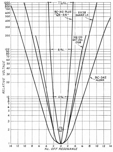
Fig. 2. A comparison of the over-all selectivity curves of two commercial receivers with the BC-312 before and after the addition of the "Q5-er." The superior selectivity of the "Q5-er" is immediately apparent. [Since the relative noise of the various receivers is approximately proportional to the area under their selectivity curves, one would also expect an appreciable improvement in signal-to-noise ratio with the "Q5-er," front-end noise figures being equal. - Ed.]
If you want the utmost satisfaction in working in our crowded bands today, it is suggested you build the single-sideband unit in October QST. However, if you can't get the necessary parts or if you want to build something less complicated, then we suggest you build this "Q5-er" and prove to yourself, as we did, that you can use more and more and still more selectivity in a communication receiver and make more effective use of our limited frequencies.
If a completely separate unit is desired there is no reason why the present second detector in your receiver could not be changed over to a cathode follower to feed a shielded line going to the "Q5-er" in a separate cabinet. This separate chassis' would then consist of a converter to 175 kc. followed by one or two stages of i.f. and then a third detector plus audio, a.v.c., noise limiter, etc. This unit could be complete with power supply. This method would require the least digging into of the original set.
P.S.: About the third essential part of the receiver, the audio, we will let you worry about that, but don't overlook the fact that a good audio filter will work wonders on c.w., and a device such as the Hetrofil(4) will take out the last heterodyne that the crystal filter wouldn't touch.
Notes
- McLaughlin, "Exit Heterodyne QRM," QST, October, 1947.
- "Q5" is used here as the abbreviation for "QRK5," the maximum readability report in the International Q Signals. Many operators incorrectly refer to the readability as "QSA (1 to 5) " - which is the strength report in the same system. - Ed.
- Note that W1DBM took off for his a.v.c. ahead of the signal diode. This was done "to develop enough U.V.C. voltage for the receiver," according to the author. However, it is not a recommended procedure because, in any receiver where the a.v.c. circuit has leas selectivity than the signal circuit, strong adjacent signals will take over the a.v.c. function. If not enough a.v.c. voltage is developed, it would be better to amplify the a.v.c. through an additional channel beyond the signal channel. If an 3-meter is used, the a.v.c. channel can have more selectivity than the signal channel - otherwise tuning is easiest with equal selectivity. - Ed.
- Woodward, "The hetrofil - An aid to receiver selectivity," QST, Sept., 1939.
Philip S. Rand, W1DBM.