Home - Techniek - Electronica - Radiotechniek - Radio amateur bladen - QST - Some facts of modulation
Corresponce we have had over the past few years indicates a rather widespread misunderstanding of the relationship between the envelope of an amplitude-modulated wave and the frequency spectrum occupied by the signal. In particular, there seems to be an impression that if by some means the output can be prevented from "hitting zero" on the downswing of modulation, the signal will be kept from "splattering," irrespective of what may happen to themodulation envelope in the process.
Unfortunately, it isn't so. The fact is that the zero axis has no greater intrinsic importance than the carrier level or the modulation up-peak or any other part of the:amplitude swing in a modulated wave. To get perspective on this point it is necessary to go back to fundamentals.
Waveform Characteristics
A sine wave is the only type of wave that contains one and only one frequency. Any other kind of wave must consist of a "fundamental" sine wave upon which has been superimposed a number of other sine waves the frequencies of which are all integral multiples or "harmonics" of the fundamental. The thesis that any waveshape can be resolved into a combination of sine waves is not particularly obvious in the ease of a complex wave such as that shown in Fig. 1, but must be accepted on the basis of mathematical proof that was given many years ago, plus the experimental fact that the individual components can be separated out by suitable equipment. The harmonic relationship of the components is fairly obvious; only frequencies that are exact integral multiples will "come out even" in one cycle of the fundamental frequency. This is necessary if each cycle of the complex wave is to be exactly like the preceding one.
Another fact of importance is this: The average value of the amplitude of any waveshape is zero. The average of all the amplitude values that the wave goes through above the reference axis is exactly equal to the average value of all the amplitude values below the axis. In the third cycle of Fig. 1, the total shaded area above the zero axis during the cycle is equal to the total shaded area below the axis. This means that the energy in the "positive" region is exactly the same as the energy in the "negative" region during each complete cycle.
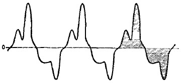
Fig. 1. This and any other periodic wave can be resolved into a fundamental and series of harmonically-related sine waves.The axis of the wave is at the point where the total areas above and below are equal - i.e., the average positive amplitude is equal to the average negative amplitude and the algebraic sum is zero.
The point deserves some elaboration. Fig. 2 represents a typical Class A amplifier grid-voltage plate-current characteristic with a sine wave applied to the grid about the operating point O. Because the characteristic is curved, the waveshape of the plate current, shown at the right, is not exactly the same as the waveshape of the voltage at the grid. If it were, the plate current would vary about the line OB as an axis, since OB represents the steady plate current determined by the operating point O. But in the actual wave-. shape of plate current the upper half-cycle is not the' same as the, lower. half-cycle. Consequently, the axis must shift to a new position such as AA', where the requirement that the average amplitude of the wave is zero is met. This changes the average plate current flowing in the amplifier and is the reason why nonsymmetrical (even-harmonic) distortion in a Class A amplifier always is accompanied by a change in d.c. plate current.
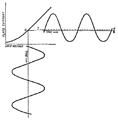
Fig. 2. In In a distorting Class A amplifier, the change in waveshape forces a change in axis, with the result that there is a shift in the plate current as read by a d.c. meter.
If the a.c. component alone is coupled out, as it might be by transformer or condenser coupling, the amplitude varies about the axis corresponding to AA' in Fig. 2. No other axis is possible, because if there were more energy on one side than the other per cycle, there would be a continuous flow of energy in one direction - Le., the transformer or condenser would be transmitting direct current.
Note that it is the average amplitude that must be the same on both sides of the axis over one cycle. There is no restriction on the peak amplitudes. It is perfectly possible to have a waveshape such that the peak amplitude on one side of the axis is very much greater than the peak amplitude on the other. Most speech waveforms are like that. Such a lack of symmetry is not the same thing as distortion in an amplifier or modulator, because no matter what the relationship between the positive and negative peaks the average amplitude of the wave as supplied to the amplifier or modulator is zero. Although such a waveshape necessarily contains more than one frequency, the component frequencies constitute the intelligence we wish to transmit. It is only a change in the waveshape that constitutes distortion - and introduces new harmonic frequencies that not only were not present in the original signal but are usually undesirable as well.
Fig. 3 shows a simple waveshape having unequal peaks. It consists of a fundamental and second harmonic combined in such a way that the positive peak greatly exceeds the negative peak. The axis of the wave is necessarily at the point where the total areas above and below it, in each cycle, are just equal.
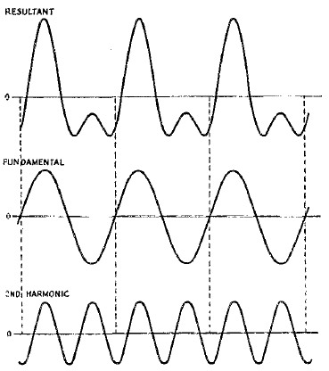
Fig. 3 - An example of a wave having a large positive peak and small negative peak. The average amplitude is still zero, since there are equal areas above and below the axis in each cycle.
Voice waves qualify as "waves" -- that is, having cyclic variations in amplitude --- because they do have definite, recurring waveforms for long-enough periods of time. If they did not, voice tones and sounds would merely be unrecognizable noise. For this reason it is possible to discuss modulation in terms of sine waves and combinations of sine waves. The simplest possible case, a single sine wave, is usually chosen for purposes of discussion. While extension to actual voice modulation would involve detailed consideration of many waveforms, such complexity is hardly justified since the principles that apply to one sine wave apply to any harmonic combination of sine waves.
Modulation and Overmodulation
In Fig. 4, the sine-wave modulating signal shown at A will produce, when applied in too-great amplitude to the modulated stage, the modulation envelope shown at B. This is typical overmodulation, with the output cut off entirely for part of the modulating cycle: As we all know, it results in a great deal of splatter. The outline of the upper edge of the modulation envelope is the waveshape of the audio signal that would be obtained from a perfectly linear detector.
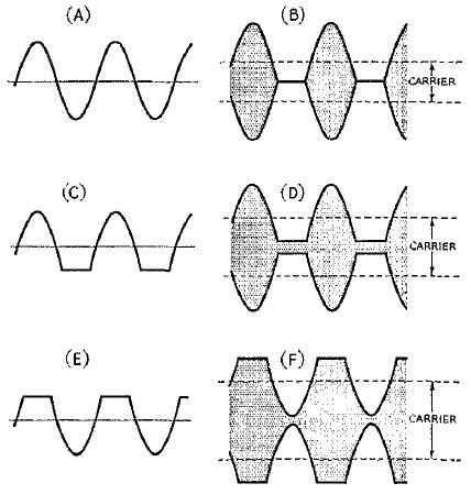
Fig. 4 - Examples of overmodulated and under-modulated waves that will produce exactly the same kind of splatter.
Now if that same audio waveshape, Fig. 4C, is actually applied to the modulated r.f. stage and the audio gain is adjusted so that the wave is not modulated 100 per cent in the downward direction, the modulation envelope will have the shape shown at D. The upper outline in this pattern has exactly the same shape as the upper outline in the pattern of Fig. 4B. The modulated wave in D will cause exactly the same kind of splatter as the modulated wave in B. Furthermore, if the modulating signal of D is turned upside down, as in E(1) and then applied to give the modulation envelope shown at F, the splatter is again exactly the same, even though this wave is not modulated 100 per cent.
The reason lies in the fact that a modulated wave consists of a carrier and a series of side frequencies, the distribution of which is solely a function of the shape (not the amplitude) of the modulation envelope --- i.e., the fundamental frequency and the harmonics necessary to make up the modulation envelope waveshape. If two modulated waves have the same envelope-outline shape, they both have exactly the same side frequencies. It does not matter whether these frequencies were actually present in the original modulating signal or whether they were generated in the process of modulation; the result is the same in either case. Also, it does not matter how they were generated, which is why the zero-output level has no special significance.
Those who doubt these statements can prove their truth for themselves. A signal of the type shown at C or E in Fig. 4 can be produced by feeding a sine-wave tone through an audio clipper, and by adjusting the clipping level one peak can be cut off at the same relative level as in the case of downward overmodulation. If the spectrums of the two modulated waves so produced are carefully explored with a receiver having a sharp crystal filter, it will be found that the number and relative amplitudes of the side frequencies will be the same in both cases. A test of this sort should be performed with a dummy antenna, of course, and an oscilloscope is necessary for checking the waveshapes. A tone of about 1000 cycles should be used so that the clipped part of the wave will stay as square as possible when passing through the subsequent audio stages. A high tone facilitates separating out the various sideband components in the receiver.(2)
When a sine wave is applied as a modulating signal to a perfectly linear modulated stage, the modulated wave has only two side frequencies. If there is distortion anywhere in the system, be it in the audio amplifiers or in the modulated r.f. stage, the outline of the modulation envelope will not be a pure sine wave. The outline then consists of a combination of the original sine wave plus a series of harmonics, just as in any complex waveform. The harmonics appear as additional side frequencies when the signal is examined by the crystal-filter method, and if their amplitudes are large enough the signal also will appear to be "broad" when it is tuned in with normal i.f. selectivity. Distortion cannot be avoided completely, because no system is perfect, but it can be kept within tolerable limits. As has frequently been pointed out in connection with using speech clippers, distortion in the audio system can be prevented from doing any harm on the air by filtering out the high-frequency audio components generated by the distortion before they can reach the modulated stage. Distortion in the modulated stage itself cannot be filtered out and invariably broadens the signal.
Peak Manipulation
As an explanation of "supermodulation" it has frequently been suggested that the negative peaks are prevented from touching the zero axis while the positive peaks are allowed to extend considerably beyond the normal 100 per cent upward modulation. By this means the signal is presumed to be kept "sharp" while putting a larger amount of power into the sidebands. In effect, the alternate half-cycles are in themselves half sine waves, but of different amplitudes.
The fallacy of this reasoning should be apparent from Fig. 5, where an actual sine wave is represented by the combination of the positive half-cycle and the negative half-cycle A. A halfcycle of somewhat lower amplitude, such as B, joined to the positive half-cycle does not make a complete sine wave, even though it may not appear to depart very far from it. But, C is also a half sine wave, and the combination of it with the positive half-cycle certainly bears no resemblance at all to a full sine wave. Either B or C combined with the positive half-cycle constitutes distortion of the original sine wave; both contain a series of harmonics of the fundamental frequency. The greater the distortion, the larger the number and amplitudes of the harmonics; i.e., the wider the channel occupied by the signal.
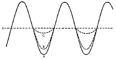
Fig. 5. Combinations of half sine waves. Only the true sine wave (top half combined with A) has only one frequency; any other combinations consist of the fundamental plus harmonics.
This type of operation is, in fact, comparable with the distorting Class A amplifier shown in Fig. 2. Amplitude modulation is somewhat anaIogous to Class A amplification, with the steady carrier replacing the steady plate current of the Class A amplifier.
The only possible benefit from such distortion, as O. G. Villard, jr., has pointed out,s is that the harmonics will not be as bad as when the signal is clipped efficiently (as it is in Fig. 4, and would be in Fig. 2 if the grid signal were large enough to cut off the plate current at the negative peak), and that therefore such a modulation envelope will not cause as drastic interference in adjacent channels as the negative chopping that accompanies straight downward overmodulation. But the argument that the splatter won't be quite as bad is hardly a recommendation. To be worthy of consideration a system should be, at least theoretically, capable of distortionless modulation. A system based on distortion in the modulated amplifier is simply one that takes more spectrum space than is necessary.
It happens that in amplitude modulation it is impossible for the modulated stage to generate an amplitude that is less than zero. On the other hand, it is easily possible to handle an amplitude greater than twice the carrier amplitude. This situation seems to be confused with the distorted type of modulation described immediately above, but the two things represent entirely different cases. An upward modulation peak that is greater than twice carrier amplitude, accompanied by a downward peak that is not as large as the carrier amplitude, does not represent distortion if the modulation envelope is simply reproducing the waveform supplied by the audio modulator. The average amplitude of the modulation-envelope waveform will still be zero. With such a modulating waveform, the average carrier level, as checked by the plate milliammeter in plate modulation, by the receiver S-meter or, most truthful of all, by a modulation monitor using a linear rectifier, does not change when the transmitter is modulated. This invariability of the carrier level in a linear rectifier is characteristic of proper operation of all pure amplitude modulation systems except those in which the carrier level is intentionally varied at a syllabic rate (controlled carrier). With this exception, a change in the carrier indication with modulation inevitably means distortion and broadening of the signal, because the lopsidedness is arising in the modulated amplifier.
- This "turning over" is merely a 180-degree phase reversal, and occurs in every amplifier stage where the signal is applied between grid and cathode and taken off between plate and cathode. It can also be brought about simply by reversing the terminals of one winding of a coupling transformer.
- However, the tone cannot be too high, because the sharp corners in the waveform resulting from clipping (which represent very high-frequency harmonics) will not be passed through the audio stages neither. In fact, it is only possible to approximate, through an audio amplifier, the waveshape that is very easily set up by downward over-modulation, particularly when the signal has to pass through a modulation transformer. This is the reason why distortion in the audio system seldom gives rise to as vicious splatter as the clipping that occurs with overmodulation.
- Villard, "Supermodulation - An explanation and evaluation," QST, December, 1950.