Home - Techniek - Electronica - Radiotechniek - Radio amateur bladen - QST - Build your own panoramic adapter
A useful adjunct for visual reception.
As most QST readers probably know, the panoramic receiver is a system that reproduces signals in visual form on a cathode-ray tube screen. With it, it is possible to "see," simultaneously, all signals within a range (100 kc. in this case) either side of any center frequency to which the receiver is tuned. This article tells how to build an adapter that can be attached to your communications receiver to provide panoramic reception, without interrupting the normal functioning of the receiver on aural signals. While it is not a project to attract the beginner, the many hams who have contact with TV servicing, or other branches of the electronics field, are sure to find it interesting and useful, and far from "too complicated."
Webster gives two definitions for the word "panorama": (1) a view in all directions, and (2) a scene that moves before one's eyes. The term "panoramic reception" could hardly be more descriptive, since both definitions can be said to apply.
Panoramic reception is the simultaneous visual representation of all received signals within a selected band of frequencies. If you were to plot a graph of frequency versus S-meter readings, as you tuned a receiver across a portion of its range, the result would be something like Fig. 1. Each pip represents a different signal in this band, and the height of each pip represents the relative amplitude or strength of that particular signal. The panoramic receiver provides a similar representation on the screen of a cathode-ray tube.
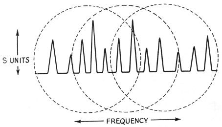
Fig. 1. Graph that might be obtained by plotting receiver S-meter readings as the receiver is slowly tuned over a band of frequencies. The portions enclosed in the dotted circles represent the signals that might be "seen" on the screen of the panoramic adapter with the receiver tuning at three different settings.
Panoramic reception is extremely useful, and a most interesting addition to the ham shack. Its versatility and importance speak for themselves. Anyone having had the opportunity to use a panoramic receiver is immediately convinced of its functional position in communications. In addition to its ability to scan a band of frequencies continuously, it provides an excellent means for checking transmitter modulation, whether a.m., f.m. or s.s.b. It is useful in checking transmitters for spurious and parasitic signals as well as key clicks. These checks can be made on the home rig and also on received signals.
Principle of operation
To obtain the graph of S-meter readings mentioned earlier, it was, of course, necessary to tune the receiver over the desired band. Since the tuning of h.f. amplifier stages is relatively broad, a limited band of frequencies might be covered with a superhet receiver by tuning only the h.f. oscillator. In the panoramic receiver, this tuning is done electronically through the use of a reactance tube. This tube acts like a variable inductance in parallel with the inductance in the oscillator circuit. When the grid of the reactance tube is driven by another (sweep) oscillator, its apparent inductance will vary continuously at a rate corresponding to the frequency of the sweep oscillator. Thus, the oscillator in the receiver will be swept back and forth over a band of frequencies. When the output of the second detector in the receiver is fed to the vertical plates of a cathode-ray tube (with horizontal sweep), the pattern on the screen will be similar to Fig. 1. The band of frequencies to be observed may be selected merely by tuning the receiver in the usual manner.
Using the communications receiver in this manner does not permit simultaneous aural and visual reception. A separate receiver might be provided for visual reception, but the most convenient (and least expensive) arrangement makes use of an adapter connected to the communications receiver. This has the advantage that the aural and visual signals are tuned simultaneously by the receiver tuning control. When adjusted normally, the signal heard in the aural channel will be centered in the visual scan band.
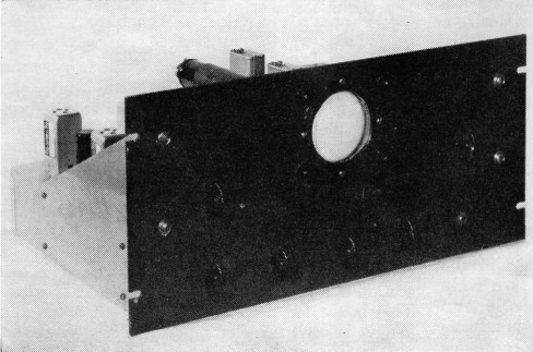
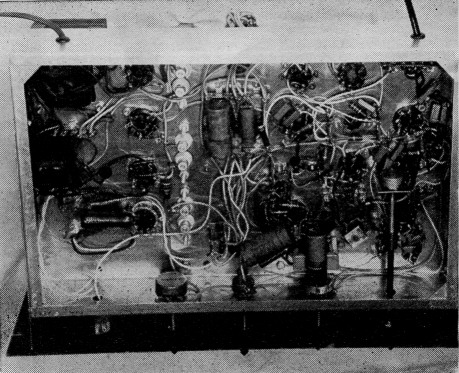
A panoramic adapter with a 3-inch cathode-ray tube. Controls along the bottom of the panel, left to right, are for equalizer, scan-band width, horizontal size, and centering. Above to the left is the vertical-size control, balanced by the power switch on the right. Immediately below the c.r.t. are focus and intensity controls;, above are two positioning controls.
With this system, the 455-kc. i.f. signal is taken from the mixer output of the communications receiver, and fed to a separate converter in the adapter. The reactance tube works on the oscillator of this converter whose output is fed into an i.f. amplifier and detector which feeds the vertical plates of the cathode-ray tube.
This article describes such an adapter. It is designed to operate with any standard communications receiver of the superhet variety having an i.f. of 455 kc. plus or minus a few kc. The receiver to which the adapter is connected should preferably have one r.f. stage to give some image rejection, but the selectivity of more than one r.f. stage will decrease the portion of the spectrum that can be scanned satisfactorily. With a single r.f. stage, the response will be flat, or nearly so, over a range of plus or minus 100 kc. from the frequency to which the receiver is tuned, giving a total scan band of 200 kc.
Basic sections
The panoramic adapter has three basic sections - a heterodyne-receiver portion converting the 455-kc. signal from the receiver mixer to 250 kc., a reactance-tube and sweep-oscillator section for scanning, and a cathode-ray tube. Fig. 2 shows these sections in a simplified block diagram.
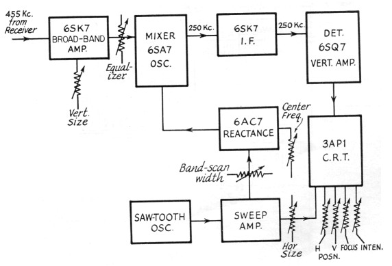
Fig. 2. This block diagram shows the essential components that go to make up the panoramic adapter.
The various controls are shown in their positions relative to the block units. Vertical size (gain) is varied by changing the bias on the broadband stage. Horizontal size is controlled by varying the amplitude of the sawtooth voltage applied to the horizontal deflection plates of the c.r.t. The converter-oscillator frequency is centered on 705 kc. (to convert 455 kc. to 250 kc.) by adjusting the bias on the reactance-control tube. The scan width is set by varying the amplitude of the sawtooth wave applied to the reactance-tube control grid. Vertical position, horizontal position, focus and brightness are adjusted in the high-voltage bleeder circuit, as in many oscilloscopes.
Circuit details
The circuit diagram of the panoramic adapter is shown in Fig. 3. The input signal is taken from the plate of the mixer in the receiver, using the coupling system shown.
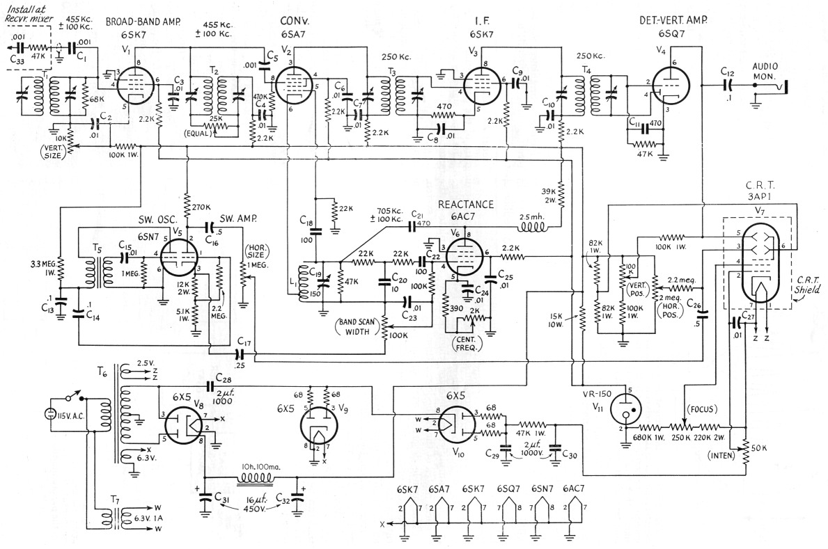
Fig. 3. Complete circuit of the panoramic adapter.
The signals are amplified by V1, a Type 6SK7 tube. This stage has bandpass circuits with adjustable shape characteristics. Roughly, the response is from 555 to 355 kc., with peaks near each end to help compensate for the attenuation at the ends of the band scanned, caused by the receiver's input selectivity. This attenuation varies from band to band on the usual communications receiver, so a unique connection of the second i.f. transformer, T2, is used to vary the response characteristic as necessary to maintain an essentially flat over-all response. This adjustment is made by a single panel control on the 25K pot at T2.
V2, a 6SA7, is the oscillator-mixer. The signal input to the adapter is always between 355 and 555 kc., with a center frequency of 455 kc. To produce the adapter i.f. frequency of 250 kc., the oscillator section of the 6SA7 must sweep over the range from 355 + 250 = 605 kc. to 555 + 250 = 805 kc., or a center frequency of 705 kc. plus or minus 100 kc.
A 6AC7 is used as the reactance tube. It is connected across the 6SA7 oscillator inductance, Lt. The center frequency (705 kc.) is adjusted accurately by varying the bias on the 6AC7. A 6SN7 is used as a sawtooth oscillator and amplifier which drives the grid of the reactance tube. The width of the band scanned is adjusted by a potentiometer. The sweep amplifier also serves as the horizontal sweep for the c.r.t. The amplitude (horizontal size) is adjusted by another potentiometer.
A 68K7 and standard 262-kc. transformers are used in the l.f. amplifier. No difficulty was encountered in adjusting the transformers to 250 kc. A 6SQ7 is used as second detector and vertical-deflection amplifier. Direct coupling facilitates signal-level indication and modulation-percentage measurements.
Power supply
The adapter's power supply uses three Type 6X5 tubes, V8, V9 and V10, and a VR-150, V11. They provide a negative high voltage for the cathode-ray tube, and a positive low voltage for the other tubes. The negative high-voltage supply employs a voltage-doubler circuit using two of the 6X5 tubes. One of the 6X5 (V10) heater voltages is obtained from a separate filament transformer. This additional filament transformer is used so that the heater-to-cathode voltage rating is not exceeded, as it would be if the tube's heater were at ground potential.
The heater voltage for the 3AP1 cathode-ray tube, 2.5 volts, is obtained from one half of the 5-volt winding normally used for the rectifier tube.
A 6X5 is also used in the positive low-voltage supply, and it has its heater connected in common with the other tubes.
Construction
A standard relay-rack panel and chassis are used, because of their popularity and because this type of construction matches a great deal of existing equipment. The chassis is 11 by 17 by 3 inches, and the panel is 88% by 19 inches.
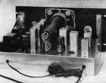
Bottom view of the panoramic adapter. The equalizer control is to the right, mounted on a bracket close to T2. To the left of the equalizer control shaft is the oscillator coil, Li, and its tuning condenser, C19. T5 is to the left of L1. To accommodate the c.r.t. length, the chassis is spaced 1½, inches from the panel.
No particular attention has to be given to the chassis layout beyond ordinary receiver-construction practice. A cathode-ray tube shield for the 3AP1 is necessary for compact layout. To do without the shield, It would be necessary to locate the transformers and choke at some distance from the cathode-ray tube to minimize the effect of their magnetic fields on the electron beam.
The brightness and focus pots should be insulated. They are mounted on fiber brackets, just behind the panel, with insulated shaft extensions through the panel bushings.
The four controls grouped around the cathode-ray tube are for focus, brightness, horizontal position and vertical position. The equalizing control is mounted as near its associated i.f. transformer as practical. It can be seen in the bottom-view photograph, at the right.
A scale or graph for the front of the c.r.t. can be constructed from thin lucite, similar to the one shown in Fig. 4. Accurate markings for modulation percentage should be made with the aid of a signal generator having the necessary calibration. For approximate modulation percentage measurements the screen can be assumed to be linear at low audio frequencies.
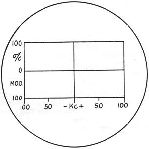
Fig. 4. Calibrating scale for the c.r.t. of the panoramic adapter.
Installation
Most receivers do not have connections for panoramic adapters. If there is any objection to the installation of a panoramic-adapter connector, connection to the mixer-tube plate can be made above the chassis by connecting C33 directly to the tube pin itself.
Rear view of the panoramic adapter. The power supply is to the left and the r.f. section to the right. Along the right end of the chassis, from the rear, toward the panel, are Ti, Vi, T2 and Va. In the middle row are T3 and V2. In line along the c.r.t. are V4, V9, T4 and Va. The empty socket is not used.
The installation of a connector is as follows: The connector is mounted on the rear skirt of the chassis and as near to the mixer tube as practicable. Any convenient type of coax connector will suffice. Css and its associated resistor in series are connected to the mixer-tube plate right at the tube socket. A lead is run from the resistor to the jack. This lead should be of coax and be kept as short as practicable.
Alignment procedure
For initial adjustment, allow receiver and adapter to warm up for 15 to 30 minutes.
The first step in alignment is to adjust the adapter's oscillator to 705 kc. A broadcast receiver can be used for this adjustment or, if the receiver to which the panoramic adapter is connected has a b.c. band, it may be used. Set the band-scan width control to zero, and the center-frequency control to midscale. Adjust C19 so that the oscillator frequency is 705 kc.
Adjust the vertical, horizontal, intensity (brightness), and focus controls for a trace on the cathode-ray tube. Adjust the horizontal size to extend the trace the width of the screen.
Alignment of the adapter's i.f. is simplified by the presence of its own cathode-ray tube and sweep circuits. Advance the band-scan width control 10 degrees to 20 degrees, and tune in any constant-carrier signal on the receiver to which the adapter is connected. A response curve will be seen on the c.r.t. This response curve is the characteristic curve of the adapter's i.f. amplifier. It is necessary to adjust the i.f. trimmers so that the response curve is in the exact center of the trace and to adjust them for the sharpest (narrowest) curve. The sharpness of this curve is a measure of the resolution of the adapter. The sharper the curve the closer the received signals can be in frequency and still be distinguishable.
Alignment of the adapter's front end is as follows: With the receiver tuned to any portion of its range that includes many signals (most of the amateur bands), set the equalizing control to maximum resistance. Adjust the vertical-size control so that signals are perceptible, and the band-scan width control near maximum. T1 is then adjusted for maximum signal strength of signals in the center of the trace. Only one section of T1 is used in the circuit. The other coil and trimmer have no effect and are disregarded.
Set the equalizer to zero resistance, and adjust one trimmer of T2 for maximum strength of signals at one end of the trace, and the other trimmer of T2 for maximum deflection of the signals at the other end of the trace. Rotating the equalizer will cause the point of maximum amplification to shift from the center to the ends of the swept band.
The approximate frequencies of the tuned circuits are: 455 kc. for T1, and 355 kc. and 555 kc. for the two circuits of T2.
Interpretation of signals
An unmodulated constant carrier appears as a deflection of fixed height, as shown in A of Fig. 5.
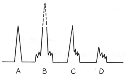
Fig. 5. Pips on the panoramic screen indicate signal characteristics. A - Constant carrier. B - Doublesideband a.m. C - S.s.b. with carrier. D - S.s.b., suppressed carrier.
An amplitude-modulated carrier appears as a deflection of variable height. Voice or music modulation causes the height of the deflection to vary irregularly. At slightly reduced sweep width a constant tone modulation of low frequency will produce a raggedness along the sides of the pip. As the modulation frequency is increased, side-bands become distinguishable. When the modulation frequency is further increased, it is possible to separate the sideband pips from the carrier by reducing the band-scan width. The higher the frequency of modulation the farther away these pips will move from the center pip, the carrier. This is shown at B of Fig. 5. Single-sideband modulation, with carrier, has a similar appearance, but is minus one of the sidebands. (Fig. 5C.)
Single-sideband suppressed-carrier transmission appears as a single pip, or small group of pips, varying in amplitude and is most noticeable by its appearance and disappearance. (Fig. 5D.)
An f.m. signal appears as many deflections spreading over a variable bandwidth. During periods of no modulation, a single carrier appears.
An m.c.w. signal looks like a c.w. signal of periodically varying height, if only the modulation is keyed. If the modulation frequency is high enough, sidebands will be distinguishable.
Noise such as static appears as irregular deflections and flashes along the whole sweep. Noise due to electrical equipment operated from the power lines is likely to be synchronous or nearly so and will stand still on the screen or drift slowly from one side to the other.
If the receiver's rejection of the images is poor (most noticeable on the higher-frequency bands), the images appear as signals, but move in an opposite direction across the screen when the receiver is tuned.
Operation
When the panoramic adapter is used with a receiver whose h.f. oscillator operates on the high-frequency side of the mixer, the lower frequencies appear on the left side of the adapter's screen, and the higher frequencies on the right. Some communications receivers operate the h.f. oscillator on the low-frequency side of the mixer on one or two of the higher-frequency bands, namely, 10 and 20 meters. When this is done, the high- and low-frequency ends of the screen are interchanged.
Most receivers operate with a.v.c. applied to the r.f. stages. If such is the case with the receiver to which the adapter is connected, the effect of the a.v.c. will be noticed on the adapter's screen. When a strong signal is tuned in it will reduce the amplitude of all the signals on the screen.
To check modulation, reduce the band-scan sweep to zero, A single horizontal line will be seen if no modulation is present. With the receiver tuned to the center of the carrier frequency, adjust the center-frequency control for maximum vertical deflection of this line. The gain control is now adjusted to center the line vertically. This d.c. level represents the strength of the carrier signal. As modulation is applied to the signal, it will appear across the screen with this line as its axis.
Circuit variations
Different sizes of cathode-ray tubes could be substituted for the 3AP1 at the builder's discretion without undue difficulty. Some of the largerscreen cathode-ray tubes require higher operating voltages, and thus would require some circuit changes.
The r.f. oscillator coil, L1, is 1.1 mH tapped at 0.2 mH. If a slug-tuned coil is used in its place, trimmer C19 can be replaced with a fixed capacitor of 82 pF.
Return-trace blanking was tried and found to be of little consequence. This is the reason for the unused socket as seen in the photos.
H.F. Priebe, Jr., W2TGP.