Home - Techniek - Electronica - Radiotechniek - Radio amateur bladen - QST - A steerable array for 7 and 14 Mc
Two band beam using fixed elements and switched phasing.
Here is an antenna system that shows what can be done under less-than-ideal conditions. The signal from W9LI is well-known on both 40 and 20 - this is an account of the interesting antenna system in use.
The antenna to be described here is of a type that is new to the amateur bands. It is useful in restricted space and gives good gain and directivity on two bands without elaborate mechanical work.
The writer has been fascinated for a long time by all the pretty pictures in Mr. Smith's pattern book(1). This book deals primarily with two- and three-tower vertical broadcast arrays, and gives the radiation pattern for every possible configuration, spacing and phasing. There are literally thousands of patterns shown, and it seemed logical to assume that some of them might have an application on amateur frequencies.
The pattern finally settled on as being most useful is bidirectional north and south and undirectional east or west. This is tailormade for the Middle West. For other parts of the country, the whole array could be given a different orientation which would be equally useful.
Here the east-west line of the beam is actually a little south of west and north of east so that to the west it goes between ZL and VK and to the east it centers on southern Europe. The north-south beam goes over South America and Japan. However, the various lobes are broad enough so that for all practical purposes 360-degree coverage is obtained.
After deciding on the pattern, three other requirements had to be satisfied. The feed system had to use coax and had to be simple to set up and adjust. The array had to work both 20 and 40 meters, and directivity and band changing had to be accomplished without the use of relays, coil changing, or any further adjustment other than the initial tuning up.
The antenna consists of three 32-foot 3-inch vertical elements mounted along an east-west line. They are made somewhat short to allow for the length of the lead to the tuning networks. The spacing is 17 feet, a quarter wavelength at twenty meters. The bottoms of the elements are ten feet above ground. Each element has a two-band network housed in a box at its base. These are tuned to 20 and 40 meters, so that the elements are voltage-fed half waves on 20 and current-fed quarter waves against ground on 40. The ground system consists of eighteen random length radials.
The directivity is controlled by the phasing and is as follows: twenty meters, north and south, all in phase; east or west, 0-90-180 degrees out of phase, with the signal going in the direction of the element with the lagging current. On 40 meters, the north-south phasing is 0-180-0, and the east-west phasing the same as on 20 meters.
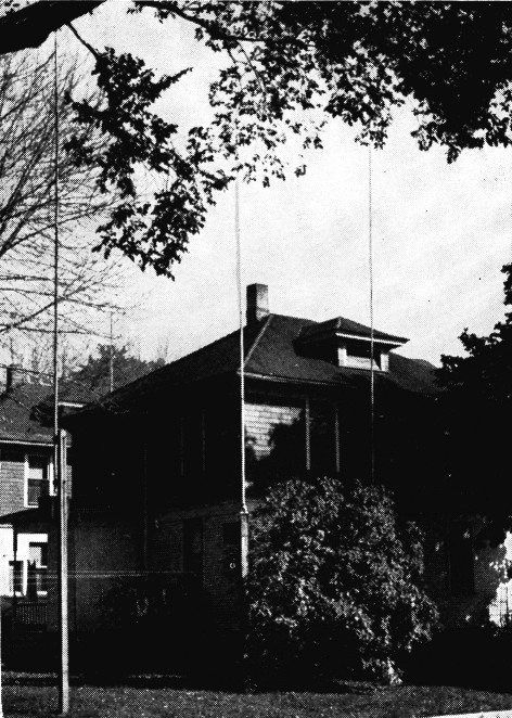
The 40- and 20-meter switch-able beam at W9LI uses three vertical elements. A ground system is buried in the lawn, as are the coaxial lines feeding the elements.
Now to get down to brass tacks as to how all this is accomplished. Referring to Fig. 1, the tuning of each element is taken care of by what might be called a two-band network. However, it isn't actually that in the sense that the term has been used before. Rather, advantage has been taken of the simple characteristics of parallel- and series-tuned circuits.
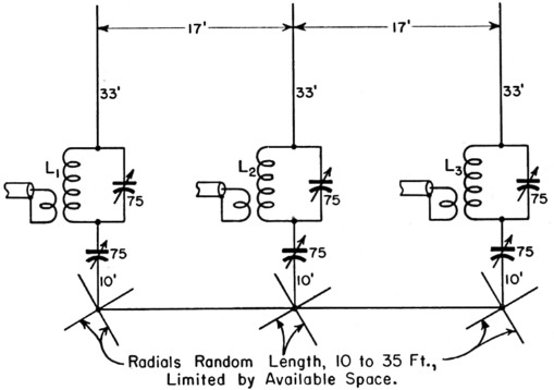
Fig. 1. The two-band beam uses three vertical antennas mounted along an east-west line. The ground system, consisting of wire radials of various lengths, is buried, as are the coaxial lines running to the shack. LI, L2, L3s - 8 turns No. 14 wire on 2½ inch diam. form.
Coupling links are 2 turns interwound at "cold" end.
The parallel-timed circuit consists of a 75-pF 3000-volt variable condenser in parallel with 8 turns of No. 14 wire on a ribbed ceramic form 2% inches in diameter. The ribs of the form are notched so that ordinarily the wire would be spaced approximately its own diameter. In winding, every other notch was used, so that the winding is double spaced on the form. At the bottom end a 2-turn link was wound in between the other turns. This circuit tunes to 20 meters and the element is voltage fed on that band.
A parallel-tuned circuit is an inductance at frequencies below its resonant frequency, so at 40 meters this circuit is just an inductance. This inductance is connected to ground through another 75-pF condenser. Connecting it in this way to the bottom end of the coil has negligible effect on 20, as the bottom end of the 20-meter circuit could be either grounded or ungrounded with no effect in performance on that band. The 7514. series condenser also compensates for the inductance in the 10-foot-long ground lead, and on 40 meters the whole thing becomes a series-tuned circuit between ground and the base of the element. The element is a current-fed quarter wave on 40 meters.
We now have 3 elements each simultaneously tuned to both 20 and 40 meters and each link-coupled to its own 52-om coax feeder. Equal lengths of coax are brought into the shack, and if all three are connected in parallel then all elements are fed in phase.
To vary the phasing to 0-90-180 degrees, two other lengths of coax are added to the original equal lengths. Referring to the Handbook formula for quarter- and half-wave matching sections gives 11.5 feet as a quarter wave on 20 meters, 23 feet for a half wave on 20 or quarter wave on 40, and 46 feet for a half wave on 40.
These lengths are coiled up in an out-of-the-way corner back of the desk.
Fig. 2 shows a 6-deck 6-position switch. This switch is mounted on the operating desk, and the feeder from each element is brought to it, as are both ends of the three matching sections. The switch adds the matching sections in series with the desired feeders to give the various choices of phasing.
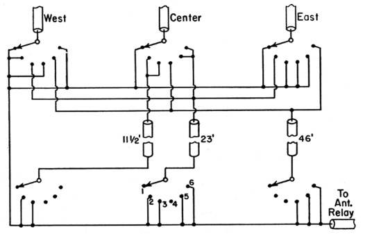
Fig. 2. Circuit of the phasing-section switching arrangement. The outer conductors are not shown connected, but they are all bonded together.
| Position | 1 | 2 | 3 | 4 | 5 | 6 |
| Direction | 20 N-S | 20 E | 20 W | 40 N-S | 40 E | 40 W |
The switch is a 6-section 6-position wafer switch (Centralab P-123 assembly with Type X sections).
If all three of the original equal lengths of coax are connected in parallel, the elements are all in phase and the beam goes north and south on 20 meters. If a quarter wave (11.5 feet) is added to the center feeder that element is fed 90 degrees out of phase. If a half wave (23 feet) is added to the east element feed, that element is fed 180 degrees out of phase. With this phasing the beam goes east on 20. Changing the halfwave section to the west element reverses the direction.
On 40 meters a half-wave section (46 feet) is added to the center feeder to feed that element 180 degrees out of phase, and the beam goes north and south.
Adding quarter- (23 feet) and half- (46 feet) wave sections on 40 gives the 90- and 180-degree phasing for east and west, just as it does on 20 meters. You will notice that the directivity on 40 is opposite to that on 20. In other words, on 40 the beam goes in the direction of the element with the shortest feeder while on 20 it goes in the direction of the element with the longest feeder(2).
The question of standing-wave ratio will probably occur to the reader in connection with this feed system. No attempt has been made to measure it. However, there is no change in the tuning of the final tank as the link is moved in to increase coupling so the s.w.r. may not be too bad.
Construction
Each element is of 21ST aluminum and is made up of six 6-foot pieces, starting at 1½ inches in diameter and tapering to Ni inch in M-inch steps. The wall thickness is 0.058 inch (17 Stubs gauge) and telescopes perfectly. The sections are held together with self-tapping screws. No guys are used and, although the tops of the elements move quite a little in a high wind, no trouble has been experienced.
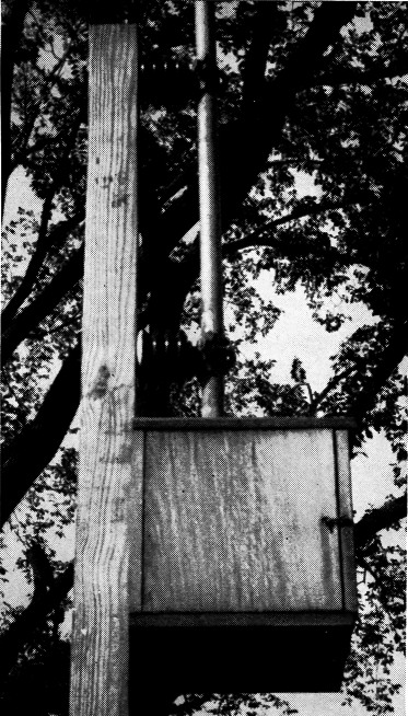
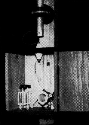
A close-up of the base of one of the elements, showing the protective housing for the matching section.
Each element is supported on two stand-off insulators on a 16-foot 4 × 4. The stand-offs are two feet apart and the poles are set four feet in the ground. The whole arrangement is very easy to erect, and the elements are so light that one man standing on a stepladder can raise them into place. The stand-offs used here have U clamps through which the elements are slid into place and then tightened down. Undoubtedly, there are other mechanical arrangements that would serve just as well.
Small wooden boxes approximately a foot square are mounted just below each element. These contain the tuning networks. The coax is fed out the bottom of the box and down the pole and then underground to the shack.
The ground system consists of eighteen random-length radials of No. 14 copper wire. Six radials are run out from the base of each pole, and the groups are bonded together at these junctions. The idea was to get as much wire as possible in the ground within the limits of a small lot.
The ground wires and the coax were buried by splitting the sod with an edging tool, and then pushing the wire into the slit. A little watering followed, and within two days all traces had disappeared.
Tuning
If an array of this type is tuned for any one direction its performance in that direction is, of course, better than it is when compromises must be made to allow switching.
A 1N34 crystal diode connected in the center of an 8-foot aluminum-tubing dipole was used as a tuning indicator. Output was taken off through two 2.5 mH chokes and by-passed for r.f. A pair of wires about a hundred feet long ran to a 1 mA meter.
In tuning a grounded antenna with such an arrangement, care must be taken to isolate the pick-up dipole from ground or else ground currents may be read instead of field strength. This error led to several weeks of head scratching before the light finally dawned.
The elements cannot be individually tuned and then fed currents with various values of phasing because of the great mutual coupling between them. This is particularly true on 40 meters where the spacing is only 3 wavelength.
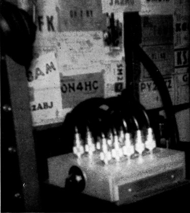
This impressive array of cables and connectors is the control point for changing the directivity of the beam.
After many trials as to the best method of tuning, the following system was finally worked out. The pick-up dipole was placed to the west with the antenna switched west, and the center element and west element were tuned for maximum field strength on 20. Then the pick-up was moved to the east, the antenna switched east, and the center element and east element were tuned for maximum. This procedure was gone over several times, to compensate for the interaction between elements. This interaction was not bad on 20.
Next, the same procedure was repeated on 40 meters without touching the 20-meter adjustments. There was found to be quite a little more interaction on this band.
Finally, both 20- and 40-meter adjustments were gone over several more times, to be sure that everything was "on the nose." All of this tuning should be done with very loose coupling to the final amplifier, to avoid pulling between the antenna tuned circuits and the final tank.
Of course this whole tuning procedure might have been done in reverse; tuning for maximum front-to-back ratio, but we were primarily interested in maximum gain.
Tuning for east and west only leaves out the north and south directions but, as it happens, north and south automatically come up OK. The only difference is that on 20 meters the loading is just a little lighter when the beam is switched north and south, and on 40 the loading is just a little heavier. A final link variable from the front of the panel takes care of the problem.
Results
Now as to results. Very good reports have been received both on domestic and D\ contacts. The calculated forward gain is 4.5 to 5 db., except north-south on -10 where it is approximately 3 db. On 20 meters the front-to-back ratio on the east-west leg is very, very good. The front-to-side ratio of the north-south beam is also exceptionally good on this band. Reports varying from five to seven S points have been received on these various ratios.
On 40 meters the front-to-back ratio in the east and west directions runs four to five S points, while the front-to-side ratio north and south is not so good. It runs about two S points on the average, but it all helps in digging that weak one out of the fourth layer.
The matching section for one of the elements. No relays are used to switch bands - the circuit takes care of it automatically.
Phased arrays using odd values of phasing have not been used in amateur work to any great extent so this antenna is presented, not as the ultimate in beams, but as a mode of operation that would seem to have distinct possibilities for our purposes.
Notes
- Carl E. Smith, Directional Antennas, Cleveland Institute of Radio Electronics, 4900 Euclid Ave., Cleveland 3, Ohio.
- If the theoretical phasings were obtained, this would not happen. However, the tuning of the coupling networks determines the phasing in the elements, and the results of the cut-and-try procedure were as described above.
James A. Turner, W9LI.