Home - Techniek - Electronica - Radiotechniek - Radio amateur bladen - QST - Overtone crystals - How and where to use them
Some circuits and their adaptation to V.H.F. gear.
The economy and circuit simplicity that are achieved through the use of overtone crystal oscillators have a price: the need for some care on the part of the user, to be sure that they are adjusted and operated properly. Overtone crystals and circuits should be thought of as tools useful in attaining certain ends, rather than as an all-inclusive technique to replace other methods in v.h.f. circuit design. Here the good and bad features of overtone circuitry are sorted out, to enable the v.h.f. man to decide whether they are right for the job at hand.
Though we've used overtone crystal oscillator circuits in v.h.f. work for quite a few years, it's a safe bet that the vast majority of all hams who employ overtone techniques have little understanding of what actually goes on in such oscillators. Several types of overtone crystal circuits were discussed in detail in QST some years back,(1) and this information appears in boiled-down form in all recent editions of the Handbook. It is suggested that the reader go over these references, as what is to follow is supplementary to them.
All overtone oscillator circuits have one basic feature in common: some method of introducing additional feed-back, beyond that normally present in simple oscillator circuits. The difference between the various overtone circuits lies mainly in the method of controlling the feedback. The idea is to give the crystal a little extra regenerative kick, on the frequency of the desired overtone, to encourage oscillation at that frequency rather than on the fundamental. There should be only just enough to accomplish this, without causing the stage to take off on a frequency determined by the tuned circuits, rather than by the crystal.
How Crystals Work on Overtones
The frequency at which a quartz plate will oscillate is determined by the way it is cut from the main crystal, and in the case of frequencies we're interested in here, by its thickness. The crystal, Fig. 1A, is deformed mechanically during oscillation, as shown in greatly exaggerated form in Figs. 1B and 1C. When the crystal oscillates on an overtone (the fundamental frequency divided by some odd number) it breaks down into separate layers. There are three layers for a 3rd-overtone oscillation, five for 5th, and so on. The overtone crystal looks like Fig. 1D and 1E, again greatly exaggerated. There is no fundamental-frequency oscillation at this time, nor is it possible to develop oscillation on even multiples.
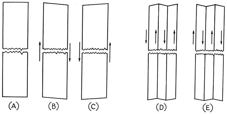
Fig. 1. How crystals oscillate at fundamental and overtone frequencies. The crystal, A, is shown at successive peaks of the cycle, when oscillating on its fundamental frequency, B and C. When oscillation is on overtones the crystal is broken down into layers, as shown at D and E.
When we remember that a crystal is actually a very thin plate, we can see why some work perfectly on their design frequencies, but refuse to oscillate on overtones. And it is obvious why extreme care must be taken in grinding and mounting crystals where overtones higher than the third are to be used. A 7-Mc. BT-cut crystal is only about 0.014 inch thick. This means that the overtone layers, even for 3rd-mode operation, are less than 0.005 inch in thickness. For 5th mode they are less than 0.003 and for 7th, 0.002 inch thick! This doesn't allow much for variations in thickness due to imperfect grinding. Even a tiny scratch on the surface may destroy overtone-mode operation entirely. The slight convex curvature usually imparted to the surfaces of standard crystals also may prevent high-order overtone oscillation.
The method of mounting,. too, may have considerable bearing on how well the crystal will work in overtone service. Pressure mounting, as in the FT-243 type of holder so commonly used, clamps the crystal in place and tends to inhibit overtone oscillation. In general, crystals mounted in the small CR-7 type of holder, with electrodes in the form of plated areas on the crystal surfaces, tend to work better on overtones than do pressure-mounted types. The capacitance of the holder may be an important factor in the attainment of high-order overtones, and here, again, the CR-7 holder and mounting method are superior.
Just about any crystal that will work well on its intended frequency will oscillate reasonably well on its 3rd overtone. Higher overtones are generally unsatisfactory with crystals ground for fundamental use. The 5th may be found, but with a majority of run-of-the-market crystals it will be low in output and very critical in adjustment. This applies to crystals between 5 and 12 Mc. Lower than 5 Mc., the crystals are thick enough so that 5th and sometimes higher overtones can be developed. Fifth-mode operation of 3.5-Mc. crystals, for instance, may be quite satisfactory. We keep hearing about this or that pet circuit that makes possible the development of high-order overtones with any crystal, but many hours of tedious adjustments with any number of circuit variations and with hundreds of crystals have convinced the writer that trying for overtones beyond the 3rd with crystals higher than about 5 Mc. is a waste of time and patience, unless crystals ground especially for overtone service are used.
Overtone circuitry
With crystals ground and mounted for overtone use, even simple circuits will work satisfactorily, provided that there is a tuned circuit at Pie overtone frequency, as in Fig. 2A. This is suitable for use between 12 and 54 Mc., the range over which relatively inexpensive 3rd-mode crystals are currently available. There is some overlap between 12 and 20 Mc. as to whether a crystal is an overtone type or not. Most manufacturers supply overtone crystals for any frequency above 12 Mc., though fundamental crystals can be made up to about 20 Mc.
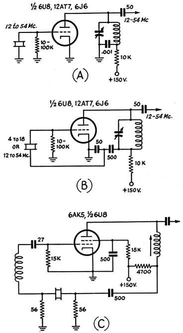
Fig. 2. Three circuits for use with overtone crystals. Circuit A, the simplest possible overtone circuit, is suitable for use with crystals processed for overtone service. Circuit B introduces more feedback, and may be used with fundamental-type crystals. The circuit at C is for obtaining high-order overtones with crystals that were processed for 3rd-overtone use. It was sent in by W9MBI, who reports use of it for direct control at frequencies as high as 216 Mc. In all three diagrams, the tuned circuits are resonated at the frequency of the desired overtone. The grid circuit in C may be tuned with a capacitor for greater range.
The simplest circuit, Fig. 2A, ordinarily does not provide enough feed-back to make fundamental crystals in the 6- to 9-Mc. range take off on the 3rd overtone, however, so some provision must be made to increase and control regeneration. In addition to the circuits we've been using for several years t there are variations such as the one shown in Fig. 2B. This circuit was first used in QST through the courtesy of the Robert Dollar Co. and W6EFT. The feed-back element here is the smaller of the two capacitors connected between the low side of the plate coil and ground. Decreasing the capacitance increases the feedback, though the value of 50 pF has been satisfactory in several applications in which we've tried many types of crystals. This takes only one more capacitor than the circuit of Fig. 2A, and it will usually work well with crystals of either the overtone or fundamental variety inter-. changeably. We've used it repeatedly for 3rd-overtone work with crystals in the 6 to 9 Mc. range, and have had no trouble getting 5th-overtone oscillation with 3.5 Mc. crystals.
In some applications it may be desirable to have the crystal oscillator as high in frequency as possible. This is particularly true of crystal-controlled converters, where energy at frequencies other than the desired one may cause birdies and spurious responses. For converter use the circuit of Fig. 2C may have merit. This was suggested to the writer by Clare Reynolds, W9MBI, of the James Knights Crystal Co., Sandwich, Ill. He uses it in v.h.f. converters, and has also had direct control of an oscillator at 144 Mc. in a low-powered 2-meter transmitter. He reports that frequencies as high as 216 Mc. have been obtained with direct control, involving overtones as high as the 11th, with this circuit.
The critical element here is the value of the two resistors on either side of the crystal. Increasing them causes more feed-back, encouraging the tendency to self-oscillation and "squegging." Dropping their value much below that specified cuts out oscillation altogether. We checked many types of fundamental crystals in this circuit in the Headquarters lab, with the usual result: In going through dozens of crystals in the range between 6 and 9 Mc., we found only two that could be made to oscillate on overtones higher than the 5th, and very few would even go this high, though all worked well on the 3rd. However, when we checked about 20 overtone crystals, higher overtones were found with ease. With any 3rd-mode crystal, the 5th and 7th modes were found in every case, and in most instances the 9th was usable. Third-overtone crystals around 12 to 15 Mc. (fundamental 4 to 5 Mc.) could be operated on their 9th, 11th and even higher overtones in some instances. Several v.h.f. crystals from the International Crystal Co., Oklahoma City, for frequencies between 40 and 50 Mc. were made to oscillate as high as 150 Mc. These were 3rd-overtone crystals in CR7-type holders.
Precautions with overtone crystals
Too many hams regard the frequency marked on a crystal holder as a fixed value, to be relied upon regardless of how the crystal is used. It should be borne in mind that even when the crystal is used at the fundamental frequency, the value marked on the holder applies only to the conditions under which the crystal was checked by the manufacturer. Changing the load capacitance into which the crystal works, using it in different circuits, or running it hotter than the manufacturer specifies, can make the frequency something quite different. Exact calibration may not be important unless you are planning to work close to band edges, but staying with the recommended operating conditions as to crystal current is important, if you want stability.
Most overtone crystals, being of the plated variety, are incapable of dissipating much heat. This means that the crystal oscillator must be operated at low power level, and with no more feed-back than is necessary to maintain good starting characteristics under load. The crystal oscillator should never be thought of as a power-generating device, and this is particularly true of overtone oscillators. The oscillator should generate a stable signal; stepping up the power should be left to succeeding stages.
When fundamental crystals are used on overtones, the frequency of oscillation may not be an exact multiple of the marked frequency. And the frequency will be different for series or parallel resonance. Moral: When working anywhere near band edges, have some accurate means of checking frequency; a crystal marking is no guarantee that you will be inside the band.
The common test for self-oscillation, pulling out the crystal to see if oscillation stops, is not applicable to most overtone circuits. The capacitance of the crystal and its holder is a part of the feed-back circuit. If there is self-oscillation present, it will almost invariably stop when the crystal is removed.
In trying for high-order overtones, it may be necessary to bring feed-back up to the point where self-oscillation develops when the tuned circuits are resonated at frequencies away from the desired overtone. If a receiver covering the range is available, the self-oscillation frequency may be checked as the circuits are varied. When the desired overtone is approached there will usually be a sudden jump in frequency to that overtone, whereupon the signal (with b.f.o. on) will become stable and musical in tone, instead of raspy and:- subject to frequency shift during even slight mechanical vibration. Adjustment of such circuits is critical, and it usually will not be right for more than one crystal.
The tuning of circuits associated with overtone crystals affects the frequency of oscillation appreciably. There may be shifts of 50 kc. or more in the 144-Mc. band when tuning overtone circuits. Thus it can be seen that they are unsuited to shaving the band edges.
To use or not to use?
From what we have said here it can be seen that the ability to work with direct crystal control in the v.h.f. range is not an unalloyed blessing. There are applications, however, where overtone techniques have much to recommend them. They are almost a must in crystal-controlled converters, for instance. Here you want freedom from birdies in the form of crystal harmonics, and you also want the energy you inject into the mixer to be as free as possible from frequencies other than the desired one. If you can get direct control at the injection frequency in your crystal-controlled converter, by all means do it. The power output required is, of course, very low, so you can achieve high stability in your converter readily. And you're not going to change injection frequencies, so critical adjustment is not an important deterrent. You're going to have to do the job only once.
Third-overtone operation of cheap and plentiful surplus crystals in the 8 Mc. range is often a convenient and economical way of controlling the frequency of v.h.f. transmitters. If circuit simplicity and low power drain are important considerations, along with low cost, overtone circuits are certainly attractive.
But suppose you're going to build an exciter that you hope to use on several bands. You want the oscillator to work with 3.5, 6, 7, 8, 12 or 14 Mc. crystals, so as to make use of a stock you have on hand. Quite likely, you'll want to have a VFO to work into the crystal-oscillator stage, too. Simplicity and low first cost are minor considerations in such a design, compared to the convenience of being able to use any type of crystal. Stability and more reliable frequency calibration are important here, too. Overtone circuits are out for such applications, obviously. You'll build this rig with all the customary TVI-prevention measures, anyway, so the possibility that unwanted multiples of the oscillator frequencies may appear in the output is of little importance. A careful consideration of all the design factors will enable you to make a wise choice as to whether overtone-oscillator techniques are attractive for the job you have in view.
Notes
Edward P. Tilton, W1HDQ.