Home - Techniek - Electronica - Radiotechniek - Radio amateur bladen - QST - Band-scanning - the easy way
A simple means of automatic receiver tuning.
This simple gadget should appeal to many, both as a novelty and as a utility. It lets you sit back and hear the sigs go by. The lazy man will find it just the thing for watching for band openings. It requires no alterations of the receiver, and can be connected or disconnected in a second or two.
Have you ever spent valuable time tuning across the 10-, 15-, or 20-meter bands without finding a single signal? Then you must have wished for an easier way to catch the band openings which are so rare in this period of the sunspot cycle. Perhaps what you need is an automatic tuner to operate the receiver while you sit in an easy chair reading QST.
Of course, any well-equipped machine shop could attach an assortment of gears, cranks and motors to your receiver that would do the job, but most hams would prefer to get the results without altering their receivers. It can be done. Most of the needed parts may even be in your junk box now.
The theory is easy. All you have to do is vary the tuning of the receiver's high-frequency oscillator at a slow rate. A motor-driven capacitor clipped on in parallel with the h.f. oscillator tuning capacitor will do the trick, and the only disadvantage is a temporary shift in dial calibration during the time the motor-driven scanning capacitor is in use. Theoretically, the r.f. and mixer tuning should also be varied, but most receivers in the lower-price brackets have only one r.f. stage and the front-end passband is so broad that little loss in gain can be noticed over a small frequency range when only the oscillator is tuned.
The unit illustrated was assembled for use with an NC-57 receiver. An old electric clock motor was used as the base and a scrap of aluminum was bent to form a mounting for a ball-bearing butterfly capacitor, as shown in the photograph. The shaft coupling was made from a small block of plastic. An APC-type padding capacitor was fastened on top and connected in series with the butterfly capacitor to vary the bandwidth scanned. The whole unit is small enough to fit inside the receiver near the tuning-capacitor gang.
Although the unit scans only about 200 kc. on the v.h.f. amateur bands, it has proved very satisfactory in detecting band openings. It has also been very interesting to operate it on bands where there is plenty of activity. At a rate of two scannings (one complete revolution of the capacitor shaft) per minute, the tuning is covered so slowly that several words can be heard from each station as it is passed, and familiar voices can be recognized.
Construction
Specifications are listed with the schematic, but as identical parts may not be available, several points in construction should be stressed. First, and most important, is keeping stray capacitance at a minimum since this will have a considerable effect on how far the r.f. stage must be detuned from normal.
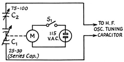
Fig. 1 - Circuit of the simple band-scanner.
| C1 | 35 pF (stator to stator) ball-bearing butterfly variable (Burstein-Applebee Cat. No. 18B1027). Also see Addendum. |
| C2 | APC type air trimmer (see Addendum). |
| M | Synchronous clock motor, 1 r.p.m. |
| S1 | Toggle. |
Second, the butterfly capacitor must turn very easily. The ball-bearing type shown is ideal, but with some ingenuity in loosening and lubricating the bearings, a plain-bearing type might be satisfactory. A capacitor with a stop cannot be used, of course.
Third, the capacitor shaft should be very carefully aligned with the motor shaft to prevent excessive bearing friction and overloading of the motor during constant use. If the alignment cannot be done accurately, a flexible shaft coupling should be used.
Fourth, any different type of motor than a clock motor should be checked for radio interference before construction is begun. The synchronous clock motor shown caused no interference while operating inside the receiver, but other small motors could generate a great deal of noise.
Fifth, the 115 volt wiring to the motor should be carefully insulated. Every amateur should realize that 115 volts a.c. is potentially just as dangerous as the higher d.c. plate voltages found in power supplies.
Adjustment
Adjusting the scanner for operation is not difficult with the following procedure:
- Set the butterfly capacitor to approximately the center of its capacitance range by running the motor through part of a revolution.
- Attach the lead clips in parallel with the receiver oscillator tuning capacitor. On the NC-57 this is the capacitor section next to the front panel. The lead from the APC padder should attach to the stator, and the other lead to the capacitor frame.
- Use a VFO, crystal oscillator, or signal generator to obtain a strong signal in the middle of the desired band. Tune in this signal with the receiver tuning dial. Since the scanning unit adds capacitance in parallel with the tuning capacitor of the receiver, the setting may be one to several hundred kilocycles higher than the normal dial setting.
- Peak the signal with the antenna-trimmer control if the receiver has one.
- Run the butterfly capacitor to its maximum and minimum settings and check these frequencies with the VFO or signal generator. Then adjust the APC trimmer to more capacitance for a wider scanning range or to less capacitance for narrower scanning range. (The total capacity added by the unit is of course equal to Cl X Cz so by decreasing C2, the total capacitance and the scanning width are reduced.)
- Repeat Steps 3, 4, and 5 until the desired range is covered.
The amount of receiver tuning capacitance in use is different on each amateur band, so the scanner must be readjusted for each band.
To restore normal receiver operation, just unclip the scanner, lift it out, and reset the antenna trimmer. This scheme is, of course, not useful with receivers whose tuning ranges are restricted to the amateur bands.
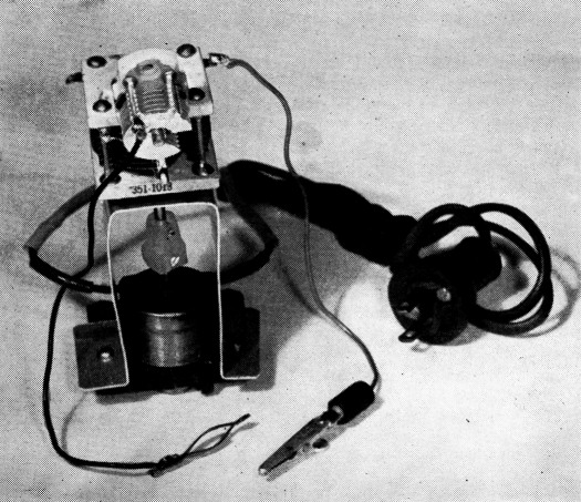
This simple band-scanner can be thrown together in a few minutes. The ball-bearing capacitor driven by the clock motor is mounted, with its shaft in line with that of the motor, on a scrap of aluminum. The range-adjusting Capacitor, C2, is suspended from C1 on stiff leads connecting it to the latter.
Addendum
The scanning capacitor used by the author, being of the butterfly type, goes through its capacitance range four times for one complete revolution of its shaft, and therefore the band is swept four times - twice in each direction. The butterfly type with ball bearings may not be generally available on the market. However, the standard-type Hammarlund VU-30 should make a satisfactory substitute, although it will take twice as long to sweep the band (twice per revolution instead of four times). The VU-30 has a maximum resultant capacitance (two sections in series) of 31.5 pF.
To obtain an idea of the range to be expected on the various lower-frequency bands, the arrangement of Fig. 1 was tried on a Hallicrafters SX-71, with a Johnson 20 pF capacitor at C1, and a 100 pF unit at C2.
With C2 set at minimum, the band-set on the SX-71 had to be readjusted about 200 kc. higher, and the tuning range of C1 was approximately 40 kc. With C2 set at maximum, the band-set had to be set about 300 kc. higher, and the range of C1 was about 300 kc.
On 40, the band-set was adjusted about 200 kc. higher, C2 at minimum, and the tuning range was about 40 kc. With C2 at maximum, the band-set was about 250 kc. higher, and the range slightly over 300 kc.
On the 20- and 10-meter bands, the band-set adjustment was only slightly different than normal. On 20, the bandspread range of C1 could be varied from about 30 kc., with C2 at minimum, to about 300 kc. with C2 at maximum. The range on 10 was about 2 Mc. with C2 at minimum, and with C2 set at about half capacitance, the entire band was covered.
K.R. Jones, W7OSL.