Home - Techniek - Electronica - Radiotechniek - Radio amateur bladen - QST - A Varactor Converter for 50 to 432
This article is not intended to go into a great deal of theory on varactors but rather describes in a "how to" fashion the construction of a parametric up-converter from 50 Mc. to 432 Mc. The unit, the circuit of which is shown in Fig. 1, was designed for use with the Heath HX-30 50-Mc. sideband exciter.
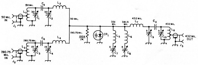
Fig. 1. Circuit of the parametric converter.
| C1,C2 | 30 pF variable (Johnson 160-130). |
| C3,C4 | 15 pF variable (Johnson 160-107). |
| C5,C6 | Gimmick, 3 turns No. 18 solid plastic-covered hookup wire twisted together; ½ inch length for 190 Mc.; ¾ inch length for 50 Mc. (Johnson trimmers may be used as shown in photos). |
| C7 | 11 pF variable (Johnson 189-5). |
| C8,C9,C10 | 5 pF variable (Johnson 189-2). |
| C11 | Gimmick, 2 pieces Ye X -inch copper ribbon overlapped Ye inch, spaced 0.020 inch. |
| CR1 | Varactor diode (Amperex H4A). |
| J1,J2 | BNC female. |
| J3 | Type N female. |
| L1 | 10 turns No. 20, ½ inch diam.; tap at 3 turns (B & W 3003). |
| L2 | 10 turns No. 20, 3/8 inch diem. (B & W 3007). |
| L3 | 3½ t. No. 18, ½ inch. diam.; tap at 1 t. (B & W 3003). |
| L4 | 3 turns, same as L1, without tap. |
| L5 | 4 turns No. 18, ¼ inch diam., spaced wire diam. |
| L6 | 3 turns No. 18, ¼ inch diam., spaced 2 times wire diam. |
| L7 | 2 turns No. 18, ¼ inch diam., spaced 2 times wire diam. |
| L8 | 2 turns No. 18, ¼ inch diam., spaced, tap at ½ turn. |
The converter gives an actual power gain of 3 or 4 in converting the signal frequency to 432 Mc. Unfortunately the author was unable to get it to take more than 0.8 watts input at 50 Mc., but 3-4 watts of output were obtained at 432 Mc. This limit is a function of pump power, which was purposely kept low to insure against varactor burnout.
The pump frequency used was at 190.75 Mc. and covers the range 431.5 to 432.5 Mc. About 10-15 watts of crystal controlled pump are required. The 190.75 Mc. pump is doubled in the converter to 381.5 Mc. and added to the 50.5 Mc. signal from the HX-30 to produce 432.0 Mc. The range with 50 to 51 Mc. from the HX-30 is thus 431.5 to 432.5 Mc. The unwanted sideband (381.5 minus 50.5) is generated also and must be supported by an idler tank (L5C7). This frequency does not appear at the output.
The Circuit
The input circuit consists of parallel-tuned circuits for both the pump frequency (L3C3) and the signal frequency (L1C1). These are lightly coupled to pi networks to couple to the varactor. Although this appears unsatisfactory at first glance, it will be noted that the reactance of the 50 Mc. pi-network inductor, L2, at the pump frequency is so high as to constitute an open circuit. Conversely, the pump inductor, L4, presents essentially no reactance at the signal frequency but the capacitor to ground, C4, does. Therefore essentially no loading of the signal frequency occurs.
The output circuit consists of series-tuned idler circuits for 381.5 Mc. (pump frequency × 2) and 331 Mc. (pump × 2 minus signal), and two resonant circuits for 432 Mc. (pump × 2 plus signal). Output is taken from a tap on the output tuned circuit.
As may be seen in the photographs, the unit is built in an inverted 4 × 6 × 2 inch chassis. The mounting plate is a 4 × 6 inch piece of i -inch-thick double-sided printed-circuit board (0.040 copper may be used if desired.) All components are mounted on this plate. Wiring is done with at least No. 18 wire going point-to-point. Most leads are inherent in the components. The varactor heat sink shown is not necessary if a solid copper chassis is used.
Adjustment and Operation
Adjustment of the converter is a little tedious since there are eight interacting controls. It is not too bad, but considerable patience is necessary.
First apply about 10 to 15 watts of pump power through an s.w.r. indicator, and adjust C3 and C4 for minimum s.w.r. A field-strength meter tuned to 381 Mc. placed nearby will serve to detect the doubling operation. Tune C8 for maximum 381 Mc. signal. Go back and forth a few times between C3, C4 and C8, adjusting for maximum 381 Mc. signal and minimum s.w.r. (they should coincide).
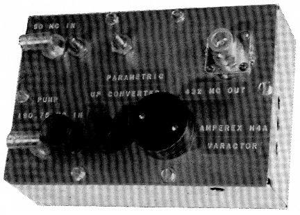
W1IGJ s parametric up-converter for transferring a 50 Mc, s.s.b. signal to 432 Mc. The round black object at the lower right center is a heat-dissipating cap for the varactor. Its dimensions are given in Fig. 2.
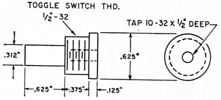
Fig. 2. Heat-dissipating cap for varactor diode. The material can be either copper or aluminum. Anode fins from a burned-out 3CX100A5 can be clamped on the stud.
Now connect a load, preferably a wattmeter, to the output and apply about 1 watt (30-per cent scale on the HX-30) to the 50 Mc. input. Tune the wave-meter to 331 Mc. and adjust C1, C2 and C7 for maximum as above. Now tune the wavemeter to 432 Mc. and adjust C9 for maximum signal. Adjust C10 for maximum output to a wattmeter or other output indicator. Note that a high wavemeter indication at 432 Mc. indicates only circulating current in L7C9 - not output. At this point it is well to go back and start again. Since all the adjustments interact to some extent you should go through at least three times. Do not be upset if your output indicator on the HX-30 goes up when connecting to the converter; this is normal. A 6 db pad between the HX-30 and the converter gives better carrier suppression since you can use more audio (sideband power) while the carrier level output of the HX-30 remains essentially constant.
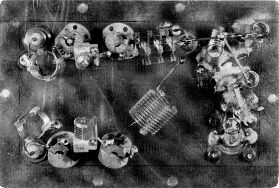
The converter is assembled on the back of the panel shown in the other photograph. The 50 Mc. circuits are at the lower left in this view, 190.75 Mc. circuits at the upper left, and 432 Mc. output circuits with idler tanks along the right side. The varactor diode is at the top just to right of center.
Conclusions
The unit exhibits good linearity when used to drive a 2C39 g.g. amplifier to about 12-15 watts output. There is some leakage of the 381.5-Mc. signal into the output; this is removed by a couple of tuned amplifiers or by a simple cavity filter. With no filter the 381 Mc. signal is at least 20 db. down from the 432 output.
This same scheme can be used to convert from a 28-Mc. s.s.b. exciter, with appropriate changes in pump frequency and idler resonances. It is possible to triple from the pump source instead of doubling, with little change in efficiency. The overall performance is nearly the same except for slightly higher pump power requirements to make up for additional loss.
Frederick R. Hess, W1IGJ.