Home - Techniek - Electronica - Radiotechniek - Radio amateur bladen - QST - Low-level blocked-grid keying
Operating conditions that influence shaping.
In an attempt to approximate break-in operation, the objective of most c.w. keying systems is to eliminate detectable output on the sending frequency whenever the key is up. The simpler manufactured transmitters manage this by keying everything from the oscillator to the final amplifier. But when an oscillator is keyed you have only two choices: Either do without shaping and thereby generate unnecessary key clicks, or do some shaping to eliminate the clicks and thereby unveil the chirp that occurred so rapidly you couldn't detect it when you didn't do any shaping. There are no alternatives, although there are many who won' t believe it. However, it can easily be demonstrated to be true,(1) and we can dismiss simple oscillator keying from this discussion.
There remain three possible methods of eliminating the oscillator signal when the key is open. One is differential keying, where the oscillator is keyed without shaping, the shaping being done in a following stage or stages.(2) The second is the conversion system, in which the desired frequency is generated by mixing two other frequencies, neither of which is near the actual operating frequency. In this case the mixer can be keyed, its output disappearing when the key is open although the other two frequencies are generated continuously. This method is generally used in s.s.b. transmitters that have provision for c.w. The third scheme, which seems to be little used at present, is the "silent" v.f.o., in which circuit design and shielding combine to allow the oscillator to run continuously. This requires low-level keying, so the shaping problems are the same as with the conversion system.
In the s.s.b. transmitter the mixer is almost invariably followed by at least one buffer amplifier, and usually both stages are operated Class A or AB1. When there is no grid current, resistance added in the grid circuit by the keying system has no effect on the operation of either the mixer or amplifier. Thus blocked-grid keying is a natural choice, since it lends itself very well to shaping both the make and break parts of the keyed character with simple RC circuits. If there is no signal leak-through(3) the mixer alone can be keyed, but often the following stage is keyed along with it.
The types of tubes generally used can be biased beyond cutoff with 50 or 60 volts. Consequently, if a sufficient range of shaping adjustment is provided, no circuit tailoring is needed for different tubes. A typical keying circuit, including bias-voltage supply, is shown in Fig. 1. It has ample adjustment range to give satisfactory shaping. If the transmitter already has grid-block keying the bias supply is already available and only the part of the circuit to the right of R1 need be used.
Installing such a shaping circuit in an s.s.b. transmitter may simply be a matter of changing some misting component values. Manufactured transmitters often have shaping of a sort, but usually the keying is harder than it should be for minimizing interference.
Control functions
In Fig. 1, R1 permits adjustment of the bias voltage to an optimum value, and R4 is a current-limiting resistor to prevent short-circuiting the supply at the extreme positions of R1 and R2. C2 is charged to a voltage determined by the setting of R1 when the key is open, and the charging time constant of C2 plus the four resistors determines the break shaping. On closing the key C2 discharges through R3i and the time constant of these two determines the make shaping. Inevitably, the decay time is longer than the rise time with this arrangement, but this is necessary for proper shaping, as will be seen.
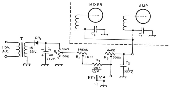
Fig. 1. Blocked-grid keying circuit for small tubes operated without grid current. Capacitances are in µf.; resistances are in ohms (K = 1000).
C1 Electrolytic.
C2 Paper; value depends somewhat on number of stages keyed, and may be as low as 0.1 µf. for keying only the mixer and following Class A amp.
C3,C4 R.f. bypasses normally in transmitter.
CR1 Silicon, 400 p.i.v.; current rating not important.
J1 Closed-circuit jack.
R1,R2,R3-Linear controls.
R4 Current-limiting resistor.
T1 "Booster" transformer, 115-125 volts at 15 ma.
Keying the mixer in a conversion-type v.f.o. is fine for preserving frequency stability, but the problems of maintaining a desired shaping through to the final output are the same as with simple oscillator keying.
All three controls, R1, R2 and R3, affect the shaping, and they are not independent in their effects. Adjustment of R3 changes the charging time constant and thus influences break as well as make. Adjusting R2 does not affect the make time constant, since only R3 is in the circuit when the key is closed. However, changing the bias voltage by means of R1 affects the shaping on both make and break.
Tube characteristics
Fortunately or unfortunately, the keying wave-shape is not determined by the time constants in the grid-block system alone; it is affected by almost every transmitter adjustment. Fortunately, because the tube characteristics contribute some useful attributes to the waveshape; unfortunately, because it is practically impossible to make any adjustment, tuning or otherwise, without affecting the keying.
Considering the keyed stage itself, Fig. 2 shows a hypothetical curve of r.f. output voltage amplitude plotted against the instantaneous value of keying bias. It is assumed that the stage will have the usual Class A cathode bias when the keying bias is zero. The curve would be typical for a tube having a variable-µ or "remote-control" characteristic. The r.f. excitation ordinarily would be adjusted so that the tube is driven just to the grid current point., but not actually into the grid-current region.
Superimposed on this characteristic is the shaping performed by the RC, circuits in the blocked-grid keying system. The blocking-bias voltage will vary with time about as shown in Fig. 3. On make, Fig. 3A, the capacitor is initially charged to the full blocking bias, and when terminals A-B are shorted by the key the bias approaches zero while the capacitor discharges through the resistor. Two initial values of bias are shown, -75 and -50 volts. On break, Fig. 3B, the now-discharged capacitor is recharged through the resistor and the voltage across it approaches the bias-supply value.
Combining Figs. 2 and 3 gives the make and break keying shapes shown in Fig. 4, A being for a blocking bias of -50 volts and B for a bias of -75 volts. Because of the tailing characteristic of Fig. 2 the output amplitude does not rise rapidly at the instant the key is closed, but for a brief period changes rather slowly. This is helpful, since the transition from zero to finite output is smooth, a condition that reduces the initial click. (Compare this with the abrupt rise in the actual bias voltage, Fig. 3A, which is a more clicky way to start the pulse.)

Fig. 2. The output amplitude from an amplifier does not rise linearly with decreasing values of instantaneous keying bias, but at first increases slowly and then more rapidly. This is a typical curve for a small tube having variable-µ characteristics. The initially flat portion of the curve adds needed shaping at the beginning of the make characteristic.
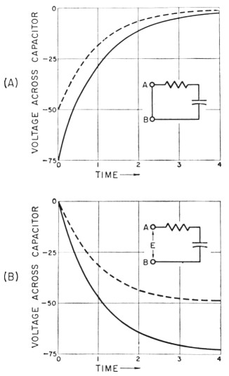
Fig. 3. Voltage rise and decay across the capacitor in an RC circuit, for two values, 50 and 75 volts, of bias-supply voltage.
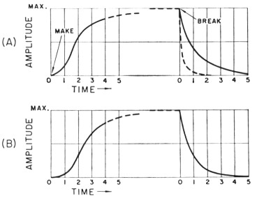
Fig. 4. Combining Figs. 2 and 3 leads to the actual shaping of the keyed character. A-initial bias-supply voltage -50 volts; B-initial bias-supply voltage -75 volts. Dashed break curve in A is for the same keying time constant on make and break; the solid curve is for a longer break time constant giving approximately the same decay time (90 per cent to 10 per cent of maximum amplitude) as rise time.
At the break end of the character the increase in negative voltage across the capacitor, Fig. 3B, is at first rapid and then becomes slower. Combined with Fig. 2 this results in a very rapid decrease in output if the break time constant is the same as on make, as shown by the dashed curve following break in Fig. 4A. A considerably longer time constant must be used if there is to be less click on break than on make. The solid curve shows the effect of increasing the break time constant so that the decay time is approximately the same as the rise time.
When a blocking bias well beyond that required to cut off the output is used (Fig. 4B) part of the change in instantaneous keying bias (Fig. 3A) has no effect, since there will be no output until the cut-off point is passed. The beginning of the character is delayed, but only slightly because the voltage is changing rapidly at first. However, the output amplitude is controlled by a slower part of the time-constant curve, which makes the initial transition from zero to finite output more slow. This can be seen by comparing the two curves for make. On the other hand, the break side is made sharper, because the bias rises more rapidly when the charging is from a higher-voltage source. This can be seen by comparing the solid break curve in Fig. 4B with the solid curve in A, both having been drawn for the same break time constant.
When the following amplifier is keyed along with the mixer the overall keying waveshape is affected, in addition, by the instantaneouskeying-bias vs. output-amplitude characteristic of the amplifier. In general, both make and break are sharpened, so the RC time constants must be lengthened to restore the same rise and decay times that were obtained when keying the mixer alone.
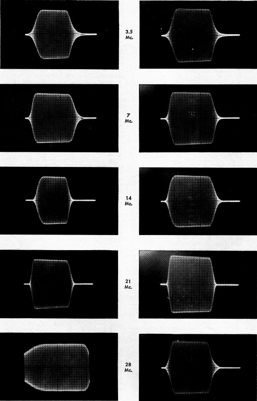
Fig. 5. Keying waveforms obtained in an experimental setup in which the keyed low-level stages were followed by three nonlinear stages, including frequency multipliers for the higher-frequency bands. Left-hand column, no adjustments made after shaping was set as shown on 3.5 Mc. Right-hand column, effect of bias-voltage adjustment under same conditions.
Following stages
Preserving the keying waveshape established in the mixer, or in the mixer and the immediately-subsequent amplifier, requires that every amplifier following the keyed stages must be linear - exactly the same requirement as for s.s.b. transmission. This means, of course, that the final-amplifier grid drive and loading must be adjusted to be the same on every frequency on which the transmitter is used. In other words, an s.s.b.-type transmitter is called for.
Since a nonlinear stage such as a Class-C amplifier or a frequency multiplier will modify the keying waveshape, the necessity for linear amplification after keying would at first glance wash out any possibility of using a conversion v.f.o. to drive a transmitter using frequency multipliers. This is true, if an attempt is made to use the same shaping adjustment on all bands. However, a keying waveform does not have to be preserved during amplification, as a voice waveform does in s.s.b. If the end result out of the final stage has proper shaping, that is all that matters. Such shaping can be done, for a price. The cost is the effort that must be spent in readjusting the keying-circuit constants on each band, which also means that the keying must be checked each time the transmitter is shifted to another band. The operating conditions in all stages following the keying also must be carefully chosen.
Fig. 5 illustrates how this can work out. The keyed signal was taken from the conversion v.f.o. discussed in another article,3 using the blocked-grid keying circuit of Fig. 1 with the keying bias applied simultaneously to the mixer and amplifier. The v.f.o. output was on 3.5 Mc. The remainder of the transmitter consisted of three stages, the first a buff er/doubler/quadrupler, the second a straight amplifier, doubler or tripler as required, and the final stage (a pair of 6146s) a straight amplifier on all bands. Cathode bias on the two low-power stages kept the plate dissipation within tube ratings with no drive, and the final stage had a combination of cathode bias and screen clamp for the same purpose. This biasing arrangement allowed all tubes to amplify immediately when the shaped v.f.o. signal began-an essential feature.
The left-hand column in Fig. 5 shows the keying waveshapes on the five bands when the shaping originally was adjusted on 3.5 Mc. and then left alone on changing bands. The normal tuning, loading and drive adjustments were made so the final-amplifier grid and plate currents were the same on all frequencies. On 7 Mc. the dots became somewhat longer but retained good shaping, and on 21 Mc. the make shape became sharper. The dots on 14 Mc. were shortened a good deal, and on 28 Mc. they were lengthened to the extent that the end of one ran into the beginning of the next. This was with high-speed (48 bauds) keying using an electronic keyer set for equal on-off times. With a straight key at slow speeds these effects would be less noticeable, except perhaps on 28 Mc., where the break would be quite soft.
The right-hand column shows what can be done simply by changing the bias control, R1 in Fig. 1, without touching either k2 or /l3. Where the dots are too light, less bias should be used, and vice versa. Careful listening with all five of these patterns showed no click, although there is some variation in rise and decay time. So it is possible to key through following frequency multipliers and amplifiers while maintaining clickless keying, even though it is not possible to retain exactly the same keying waveform on all bands.
A frequency multiplier following a keyed stage ordinarily will tend to speed up the rise and decay times, since its output is more sensitive to excitation voltage than is the case with a straight amplifier. However, this may be altered, in a given transmitter setup, by the drive settings necessary for getting the required multiplier output. The 28-Mc. pattern at the lower left in Fig. 5 is actually softened instead of sharpened, and the dots are much longer. The reason for this is that the v.f.o. keying had to be quite soft in order to produce the patterns shown for the other bands where drive requirements and tube response were different; when the v.f.o. output was increased for equal 28 Mc. drive, the soft v.f.o. keying took over. There is obviously no general rule to be applied - other than to adjust the keying for each band.
Break-in
Just because low-level keying is used, real break-in operation does not follow as a matter of course. With either multiplier- or s.s.b.-type circuit design the keyed stage has to be followed by amplifier stages that take plate current with the key open. So long as plate current flows these stages will generate noise which can interfere with reception. The noise has to be eliminated before break-in is possible.
This question becomes more acute when there is added to it the problem of how to use the same antenna for transmitting and receiving. We have found, for example, that a final stage by itself will not generate enough noise to matter when separate sending and receiving antennas are used, but this may not be true when the final stage and receiver are coupled together through a tube t.r. switch.4 But even when separate antennas are used it is generally impracticable to let every stage remain in operating condition while the key is open. The reason is that the relatively-small amount of noise generated in the earliest non-keyed stage is amplified through the rest of the transmitter, and enough is radiated by the transmitting antenna to make weak-signal reception practically impossible around the nominal transmitting frequency.
In the test setup which produced the pictures in Fig. 5 the noise was overcome by keying the driver for the final stage along with the v.f.o. It was quite simple to do this by means of the circuit shown in Fig. 6. The tube, a receiving-type power pentode, has a cathode resistor, R2, which with the key closed develops enough bias to hold the plate current within the plate-dissipation rating without drive. The principal operating bias is obtained from grid rectification and R1. The tube is instantly ready for drive when the key is closed, so the make shaping can be done in an earlier stage. When the key is opened, the keying bias during break rises to the final value at the grid of the tube just as it does in the other keyed stage or stages. Thus the tube continues to operate until the break shaping is over. Note, however, that this speeds up the decay of output during break, so the keying time constant must be adjusted to compensate.
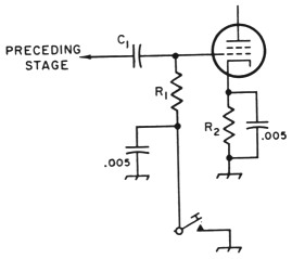
Fig. 6. This circuit can be used for keyirg the transmitter driver stage for eliminating key-up noise. The key shown above is identical with the key in Fig. 1; this wiring is simply in parallel with the shaping circuit across the key terminals. The make time constant is negligible, allowing the make shaping to be done in an earlier keyed stage. Break time constant is controlled by the shaping adjustments.
The same method certainly could be applied to a Class AB1 final amplifier. It is doubtful that it could be made to work satisfactorily with a final stage that takes grid current, because the resistance introduced by the shaping circuit into the grid-return circuit would be too large for normal grid-leak operation.
In summary, it can be said that with sufficient care in design and adjustment, and the willingness to keep continuous watch on the adjustments to be sure that they are right, it is possible to get clickless keying, and may even be possible to work break-in, when the transmitter is keyed in a low-level stage. However, it would appear that the break-in question could be answered more straightforwardly by using differential keying with all shaping done in the final stage. With that system the transmitter noise output can be eliminated, and once the shaping time constants have been set it is only necessary to see that the final stage drive and loading are adjusted for the same operating conditions on all bands - an adjustment that can easily be checked by measuring the plate and grid currents.
Notes
- Some oscillators are of course better than others and will show less frequency change when the plate and grid voltage are varied, as they must be when the oscillator is keyed. Als), since the instability is about proportional to frequency, chirp is roughly only about one-eighth as bad on 3.5 Mc. as on 28 Mc., other things being equal. This, combined with the inability of many operators to recognise chirp anyhow, at least in small amounts, accounts for the fact that oscillator keying often produces c.w. signals acceptable to the majority on 3.5 and 7 Mc., even when enough shaping is used to reduce clicks to an also-acceptable level.
- Geodrnan, "Chirp-free break-in keying," QST, October, 1953. See also the chapter on keying in The Radio Amateur's Handbook.
- This and other problems in the design of a stable conversion-type v.f.o. suitable for keying are discussed in "V.F.O. Stability - Recap and Postscript," QST, September and October, 1966.
- An alternative to the tube t.r. switch is a keyed antenna relay, which requires a high-speed relay capable of carrying (but not breaking) the antenna or transmission-line current.
George Grammer, W1DF.