Home - Techniek - Electronica - Radiotechniek - Radio amateur bladen - QST -The field-effect transistor as a stable V.F.O. element
The October 1960 issue of QST described a v.f.o. that at the time appeared to be as stable as possible without going to extreme expense.(1) Many of these v.f.o.s. were built successfully by the author and others. Moreover, variations of the original oscillator were constructed for frequencies as high as 12 Mc., and some physically smaller units were designed for mobile operation. New developments in transistor technology, however, now make possible a v.f.o. that not only provides excellent stability at moderate cost but a number of other important advantages as well.
The recently-announced RCA 3N128 is a high-frequency, high-transconductance version of the silicon insulated-gate field-effect transistor. This device, using the metal-oxide-semiconductor construction, is more commonly referred to as an "MOS" transistor. From a very practical point of view, the MOS transistor performs more like a vacuum tube than any of the other semiconductor devices. It combines the vacuum tube's very high input impedance with the transistor's very low power dissipation and operating potentials. These basic characteristics provide the v.f.o. designer with two major advantages:
- Operating potentials can be obtained directly from a 12-volt source, such as an automobile battery, dry battery, or low-voltage power supply.
- Because so little heat is generated within the device, it becomes practical to enclose the transistor in the box with the tuning coil and capacitors, instead of mounting it outboard as was necessary for the vacuum-tube v.f.o.
Circuit Details
Fig. 1 shows that this oscillator is basically of the Colpitts type. The tuning range is spread over practically all of the tuning dial. As in the previous tube models, the effect of changes in transistor element capacitances is minimized by use of a voltage divider consisting of C4, C5, and C6, with the transistor connected across two of them. The use of fairly large values at C5 and C6 almost completely supresses the effect of transistor capacitances. A radio-frequency choke provides the needed low IR drop for the source current of the MOS transistor. A resistor was tried, but the voltage drop connected with it over-biased the transistor.
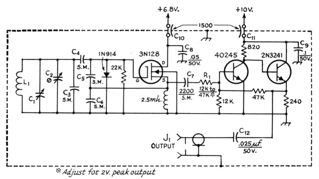
Fig. 1. Circuit diagram of the variable-frequency oscillator and buffer. Except as indicated, capacitances are in pF. Resistances are in ohms (K =1000); resistors are ½-watt composition.
C1 Double-bearing variable (Millen 23100 or 23050-see table below).
C2 25-pF air trimmer (Hammarlund APC-25 or equivalent).
C3,C4,C5,C6 Silver mica; see table below for values.
C7 2200 pF silver mica
C8,C9,C12 Ceramic disk.
C10,C11 Feedthrough type.
J1 Coaxial connector, chassis mounting.
L1-See table below.
R1 12,000 to 47,000 ohms; select for 2-volt peak output level at input to transmitter.
RFC1 Miniature 2.5-mH r.f. choke, iron core (Millen J300-2500).
Because the MOS transistor by itself will not provide rectified gate current, a silicon diode is used in the gate circuit. This diode contributes considerably to the frequency stability of the oscillator by making possible a degree of automatic bias comparable to that obtainable with a vacuum tube.
The v.f.o. output is taken from the MOS transistor oscillator through a two-stage negative-feedback amplifier which performs two basic functions.
- It greatly minimizes the effect on the oscillator of a change in output conditions.
- It provides a convenient means of adjusting the output voltage of the v.f.o. by altering the value of R1.
As in the tube model, the use of silver-mica capacitors assures a fairly stable temperature characteristic.
This transistor analog of W2YM's p tube v.f.o. (described in October 1960 QST) uses a newly-developed high-frequency FET. With its isolation amplifier, the oscillator delivers the same output as its tube predecessor - but from a low-voltage d.c. supply. Specifications are given for two popular v.f.o. frequency ranges in addition to the original 3.5-4 Mc.
| 3.5-4.0 Mc. | 5.0-5.5 Mc. | 8.0-9.0 Mc. | |
|---|---|---|---|
| L1 No. of turns | 17* | 14¾* | 11½** |
| L1 Wire size | 20 | 20 | 18 |
| L1 Turns/inch | 16 | 16 | 8 |
| L1 Diam., inches | 1 | 1 | 1 |
| C1, pF | 100 | 50 | 50 |
| C2, pF | 25 | 25 | 25 |
| C3, pF | 100 | None | None |
| Ca, PF | 390 | 390 | 270 |
| C5, pF | 680 | 680 | 560 |
| C6, pF | 680 | 680 | 560 |
* B & W 3015, Polycoils 1748, AirDux 816T.
** B & W 3014, Polycoils 1746, AirDux 808T.
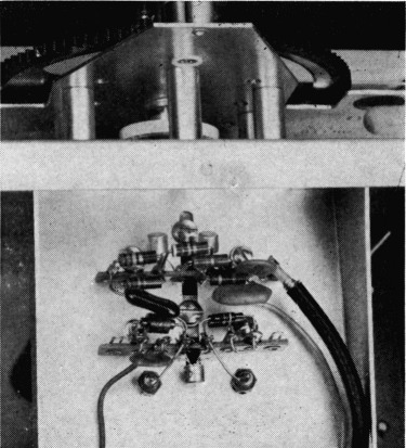
Oscillator and buffer components are mounted on two tie-point strips underneath the tuned circuit. The lower strip supports the oscillator components, with the 3N128 projecting downward from the center of the strip in this view. The upper strip is for the two-stage buffer; in this case the transistors project upward on either side of the mounting screw. The short length of coax cable runs to the connector on the rear of the shield box.
Mechanical details
Like the vacuum-tube unit, the MOS v.f.o. requires great care in the mounting of the oscillator components. The complete v.f.o. is housed in a 4 × 5 × 6-inch aluminum utility box. The MUS oscillator, less its tuned circuits, is mounted on an H. H. Smith No. 10711 terminal strip, as shown in the bottom view. The two-stage amplifier is mounted on a similar st rip. Power is carried to the closed unit by means of 1500-pf. feed-through capacitors mounted at the rear of the ut ility box along with the 25 pF frequency-setting capacitor. The tuning capacitor should be a high-quality, two-bearing type: in this particular oscillator, a Millen 23100 MIFF was used.
Maximum rigidity of the oscillator circuit is obtained by the use of a special bracket formed from one of the utility box covers. The box cover material is soft aluminum and can be bent easily with the aid of wood blocks and a vise. Hardwood blocks and a hammer are used to make the bends square and sharp. When bolted securely to the front and back of the oscillator box, the bracket not only supports the circuit components but helps stiffen the box itself.
To facilitate mounting the variable capacitor, the holes for the mounting feet are slotted. In addition, during assembly the shaft nut and mounting spacers are tightened to the side of the box first, and then the 6-32 screws for the feet are tightened. Special clamps designed to hold the coil are cut from thin lucite or polystyrene in strips % inch wide and 2M inches long. Holes are drilled at both ends of each strip so that they can be bolted to the standoff insulators.
The silver-mica capacitors, which form a part of the tuned circuit, must be mounted so that there is no possibility of motion. Small feed-through insulators are used as tie points to hold them as shown in the inside top view. For maximum reinforcement of the entire unit, new covers were cut from u/s-inch aluminum panel stock and fastened to the boxes with a liberal number of self-tapping screws.
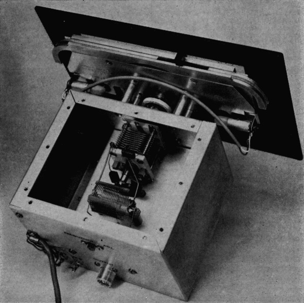
The tuned circuit is supported by a bent aluminum sheet extending from the front to the rear of the 4 by 5 by 6-inch box. The trimmer capacitor, C2, is mounted on the rear wall, as are also the coaxial output connector and feedthrough bypass capacitors for the power leads.
Although any suitable dial and panel arrangement could be used, the particular one shown employs a Millen 10037 "no string" panel dial. The dial is mounted on a small panel and the assembly in turn is bolted to the v.f.o. box with 1W1-inch metal pillars. Though large, the dial is free from any noticeable backlash and provides adequate illumination and an easy-to-read scale.
The panel is provided with a single-pole, double-throw switch, which can be connected so that in the "spot" position only the v.f.o. supply can be turned on, but in the transmit position this function is transferred to the main transmitter power-supply control so that it is activated by the transmit/receive switch.
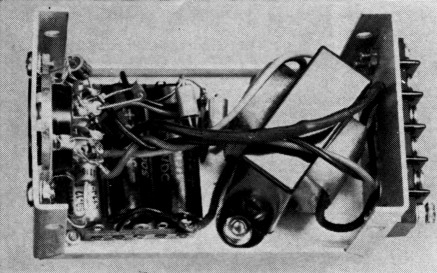
Inside the power supply, which is assembled on the flanged section of a 2¼ by 2¼ by 4-inch Minibox. Components in this unit may be mounted in any convenient way. Connections going to the v.f.o. are brought out through the octal socket at the left; a.c. input and control terminals are on the strip at the right.
Fig. 2 shows a suggested power-supply circuit for 120-volt, 60-cycle operation. The regulator in this circuit also can be used for mobile work.
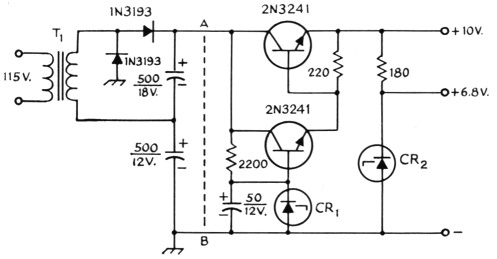
Fig. 2. Circuit of regulated power supply for the FET v.f.o. Capacitances are in µF, capacitors are electrolytic. Resistors are ½ watt. For mobile use, a 12 volt car battery may be substituted for rectifier/filter supply to the left of line AB.
CR1 10-volt 1-watt Zener diode.
CR2 6.8-volt 1-watt Zener diode.
T1-6.3-volt 1.2-amp. filament transformer.
The vacuum-tube v.f.o. article prompted many requests for information on how the unit could be adapted for use at other frequencies. Generally speaking, this MOS transistor circuit is useful at any frequency up to and including the 144-Mc. band. For those interested, coil and capacitor information is provided for two additional frequency ranges: a 5 to 5.5-Mc. range for s.s.b. transmitters, and an 8- to 9-Mc. range for 50- and 144-Mc. transmitters.
Performance
The performance of the v.f.o. leaves very little to be desired with regard to achieving minimum frequency drift. For example, the 3.5-to 4-Mc. unit described showed a frequency drift of less than 30 cycles in two hours after a 30-second warm up. The 5- to 5.5-Mc. unit drifted less than 50 cycles for the same period, and the 8- to 9-Mc. unit drifted slightly more than 200 cycles.
Acknowledgement
The author wishes to acknowledge the valuable aid given by Mr. L. Kaplan in the design of the two-stage feedback isolation amplifier.
Notes
G. D. Hanchett, W2YM.