Home - Techniek - Electronica - Radiotechniek - Radio amateur bladen - QST - The fine art of improvisation
Improvising in the ham workshop may lead to new ways for solving electrical and mechanical problems. The net result is often a savings in time and money!
"I gave up on building ham gear because parts are hard to find and they cost too much." Ever hear that comment? Perhaps you've said it to yourself in silent despair. Actually, parts are not hard to find, and most of them need not be purchased at top price. But, there are some items that are very expensive and hard to locate when we attempt to buy them new. It is conceivable that we might have to spend $15 for a tuning capacitor and a vernier drive, when the circuit with which it will be used contains only $3 worth of small parts. Prices of items such as tuning capacitors, drive mechanisms, cabinets, slug-tuned coils and meters (purchased new at nonsurplus prices) can discourage even those builders who have a large Amateur Radio budget. The cost, plus the present-day agonies of being socked with back orders and "out of stock" notifications from mail-order dealers, does tend to make us think parts are hard to obtain.
What alternatives do we have? The ingenuity of a true experimenter must be summoned from within if speedy solutions to these common problems are to be found. In decades past, it was a regularly practiced art among hams to solve design and procurement problems by using materials on hand. Most hams were inveterate experimenters when I became involved in Amateur Radio. It was considered a challenge to come up with new electrical and mechanical ideas, then share them with other amateurs. In those days, it was often a stimulating learning experience to get on the air and talk about circuits and projects.
Each of us has the potential to build radio equipment, to find shortcuts to design objectives and to enjoy using something we built ourselves. Let's consider some practical ways to use parts in applications for which they were not designed. Perhaps some of these concepts will solve a design problem for you.
Experimental Tuning Methods
Transmitters and receivers require some type of signal source, and generally this local oscillator (LO) is tunable. The conventional techniques for changing a VFO frequency are by means of a fixed-value inductor and variable capacitor or a fixed- value capacitor and a variable inductor, or by employing a VVC (voltage-variablecapacitor) diode. A quality double-bearing tuning capacitor that rotates smoothly is not only hard to find these days, it can be bulky and very expensive. Much of our miniature homemade equipment would be more practical if a tuning capacitor could be avoided for changing the oscillator frequency.
How might we contrive a simpler, less expensive method for tuning a VFO? I developed an interesting circuit for use in a very compact receiver (Fig. 1) that qualifies as a simple, inexpensive tuning technique. I had some reservations about how it might work, but after breadboarding a test circuit, I was pleasantly surprised with the results. For lack of a better name, I call it "reactance tuning." Fig. 1 shows the details of the test circuit in which I tried the idea. R1, which is a high-quality Allen Bradley (A/B) potentiometer, is located close to C2 and L1 in order to keep the leads from R1 as short and direct as possible.
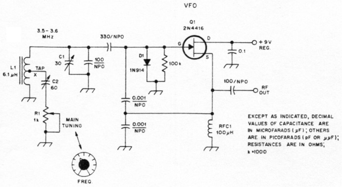
Fig. 1-Typical circuit for a VFO that uses a 2N4416 or MPF102 FET. Tuning is by means of Al In series with C2. C2 sets the frequency spread provided by R1. This arrangement is useful when an air-variable capacitor and vernier drive are not desired. It can lead to a very compact VFO assembly. The tap position on the coil (L1) and the maximum capacitance provided by C2 determine the maximum tuning range available.
Why does this system work? Well, as R1 is adjusted, the presence of the capacitance of C2 (a trimmer) is more prominent in the tuned circuit. The series combination of C2 and R1 fore a capacitive reactance and resistance that cause a frequency shift as RI is adjusted. The smaller the value of resistance at R1, the lower the operating frequency, because the capacitance of C2 will be more effective.
What are the bad features? No innovation is necessarily perfect, and this applies to the technique illustrated in Fig. 1. The tuning is nonlinear. That is, the frequency is spread out at the niaximum-resistance end of the R1 range, and it is somewhat compressed at the minimum-resistance end. Also, if a poor-quality control is used at R1, you may hear a slight scratching noise as the control is adjusted, while listening to the output of a receiver in which this VFO is used. It should not cause a problem if we use the VFO in a transmitter.
The amount of frequency shift available depends on two things: the position of coil tap X on L1 of Fig. 1, and the setting of the trimmer capacitor, C2. The farther the L1 tap is above ground, the greater the frequency change as RI is adjusted. Similarly, the greater the capacitance of C2, the larger the frequency change. I had no trouble covering all of the 40-meter band when the coil tap was close to the high end of L1. In a practical application, it is best to limit the frequency change to 25 or 50 kHz. This provides better bandspread when RI is adjusted. A vernier-drive mechanism can be coupled to R1 if frequency excursions greater than, say, 50 kHz are desired.
I did not observe any degradation in VFO frequency stability when comparing this tuning method with that of variable-capacitor tuning while using the same oscillator module. There is, however, a point in the tuning range of RI where the loaded Q of the VFO tuned circuit will take a dip. When this happens, the VFO output will drop slightly and the output waveform linearity will change. In most practical applications, you will not be able to detect this effect.
As an alternative to the use of a vernier drive attached to RI, we might consider using a bargain-priced 10-turn, carbon-composition control with a suitable 10-turn counter dial. Wire-wound controls must be avoided because they are inductive.
Another Tuning Trick
I tried another idea that I had in mind for a number of years. The circuit for this one is given in Fig. 2. L2, a modified carbon control, is fashioned by removing the metal cover from a standard-size potentiometer, then removing (carefully) the semicircular carbon element from inside the control. I was able to snap this element loose by prying it up near the tabs of the control. The thin phenolic base material broke easily. I used this element as a pattern and cut out a new element from flashing copper. Brass would work, also. Silver plating would help to ensure minimum corrosion, but it is not necessary to add silver plating if the control will be used regularly.
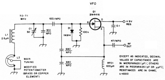
Fig. 2-A variation of the circuit of Fig. 1. In this example. the tuning mechanism is a potentiometer that has been modified to become a small variable inductor (see text).
The new element is glued in place, and the ends of the insert piece are soldered to the two outer lugs of the old control. Be careful to avoid getting epoxy glue on the upper surface of the metal element, or erratic operation will result.
Refer again to Fig. 2. L2 is a small variable inductor we made from the potentiometer. It comprises a part of the overall circuit inductance by virtue of its being in series with L1. As L2 is adjusted, the VFO frequency will change. The higher the operating frequency of the VFO, the greater the frequency change caused by L2. Also, the higher the C-to-L ratio of the VFO, the more effect you will observe when L2 is adjusted. The frequency shift obtained with this method is substantially less than with the circuit of Fig. 1, at least with the circuit values given. A 10-kHz shift was observed.
Incremental band-segment selection can be had with either circuit (Figs. 1 and 2) by adopting the method shown in Fig. 3. S1 is used to add capacitors to the VFO tuned circuit, and R1 or L2 can be used in the manner described previously. Perhaps a miniature DIP switch can be added to operate as SI when compact equipment is being built. The values of capacitors C3, C4 and C5 will determine the coarse tuning range. Trimmers may be substituted for these fixed-value capacitors, which will enable you to have the tuning ranges overlap.
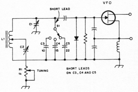
Fig. 3 - S1, C3, C4 and C5 have been added to the circuit of Fig. 1 to provide coarse frequency increments. R1 tunes the VFO through each of the three ranges.
Simple, Homemade Tuning Capacitor
Large frequency changes are possible if we use a low-capacitance variable capacitor that is connected to the high end of a VFO tuned circuit (junction of Cl and L1 Fig. 1). A simple mechanism is illustrated in Fig. 4. It is one that I developed during my search for simple VFO tuning methods. The drawing at A of Fig. 4 shows a side view of the assembly I constructed. A piece of 1/4-in x 20 iron bolt is used as the tuning shaft. The front plate of the tuner is a piece of copper-clad PC board. The hex nut is soldered to the inner surface of this end plate, as shown. A disc of copper or brass serves as the capacitor rotor. It is soldered to the end of the bolt that is opposite the knob. I used a 1-inch-diameter disc, and made certain it was at an exact right angle to the bolt when I soldered the two pieces together. A spring is used between the disc plate and the front-plate bearing nut to prevent wobbling and undue backlash. PC-board braces are soldered (four each) to the front bracket and stator-plate bracket to ensure physical stability.
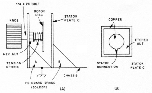
Fig. 4 - Mechanical details for a homemade disc tuning capacitor. A tension spring ensures mechanical stability of the rotor portion of the variable capacitor. Side brackets also help to keep the unit mechanically rigid. The detail at B shows how the stator disc is etched on PC board material.
Drawing B of Fig. 4 shows how I made the stator plate. It is a piece of PC board with an outer border and disc that were provided by etching with ferric-chloride solution. Glass-epoxy circuit board is re commended in the interest of high dielectric quality and physical strength. A piece of thin Teflon sheet is glued to the surface of the stator disc to prevent short circuiting of the stator and rotor discs. Polyethylene sheeting is suitable if you have no Teflon on hand. The capacitance range I obtained with this unit was 0 to 18 pF with the 1-inch diameter disc plates. The closer the plates are to one another, the greater the capacitance and the faster the tuning rate. The rotor disc is grounded by means of the bolt-to-nut connection and by virtue of the frontend plate being grounded. Those skilled in machine work should be able to improve on this design. The disc-tuning method is by no means a new concept. VHF cavities and amplifiers were tuned by this technique for many years. But, I don't recall seeing it applied to HF circuits in this manner.
Another Capacitor Idea
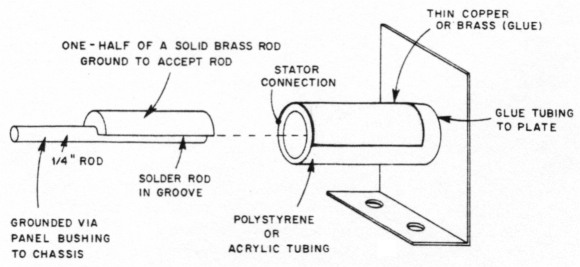
Fig. 5 - A cylindrical format provides still another tuning device that can be made at home. The rotor unit is semicircular brass or copper to which a 3/4-inch-diameter tuning rod has been soldered. The stator section is a piece of plastic tubing to which thin copper or brass sheeting has been glued (see text).
A cylindrical tuning capacitor can be fashioned as shown in Fig. 5. The rotor is slipped inside the stator tubing. When the metal half-rod of the rotor is immediately adjacent to the metal half-round outer conductor of the stator tube, maximum capacitance will exist. The rotor shaft is rotated by means of a knob or vernier drive to operate this capacitor. The larger the two half-round conductors (circumference and length), the greater the maximum capacitance of the unit. The mechanical aspects of this device can be improved markedly by those of you who are adept at building mechanical gadgets. Certainly, a fine assembly could be turned out by a craftsman. The point being made here is that this is just another method for constructing a homemade variable capacitor. There are many other unique ways to construct home-built tuning capacitors, but we shall not go into a lengthy discussion about them.
Generating Innovative Ideas
I have been asked, "How do you come up with so many unusual gadgets?" I think the best reply I can offer is to say that examination of a conventional component should suggest numerous ways to simplify it at a savings in cost. Some inventors do not generate new ideas. Rather, they pick up some ordinary object, such as a paper clip, then ask themselves, "What can I do to improve this thing?" We might also ask ourselves, "What don't I like about this paper clip?" The next step is to devise a new paper clip that no longer has the design fault. Bingo! A new patent can result! This general philosophy can be applied to making our own radio components from readily available materials. You can try your ideas, and you need not be ashamed if they don't work the first time or even at all.
In Conclusion
When you are working with the circuits of Figs. 1 and 2, it is important that the Q of L1 be as high as you can make it. If the Q is quite low, the addition of R1 or L2 could cause the VFO to cease oscillating at some point in the tuning range. Therefore, I suggest that you use a T68-6 toroid core for frequencies above 4 MHz. The wire size should be as large as can be wound easily on the toroid core. This will reduce the coil resistance and enhance the Q. The same rule applies if you use a slug-tuned inductor: The core should be for use in the upper part of the HF spectrum. High-quality capacitors should be used also. The NPO units specified are entirely suitable, and will ensure minimum WO drift. Silver-mica capacitors can be used, but will cause considerably more drift than will the NPO ceramic units.
Should you develop some noteworthy circuit innovations, please consider sharing them with others through the pages of QST. Detailed descriptions can be submitted as articles. Short explanatory narratives may be just right for the Hints and Kinks column.
W1FB, Doug DeMaw.