Home - Techniek - Electronica - Radiotechniek - Radio amateur bladen - QST - Improved anode parasitic suppression for modern amplifier tubes
It's not your imagination: Today's high-power tubes are tougher to tame than their predecessors. Here are up-to-date parasitic-oscillation cures that succeed where traditional techniques fail.
What's a parasitic oscillation?
Ideally, an amplifier just amplifies: You put a signal in and get the same signal out, only stronger. (Some distortion also occurs in the process, but this usually isn't much of a problem in a circuit of sound design.) Sometimes, though, an amplifier does more than amplify: It actually generates signals on its ownoscillates - on a frequency or frequencies far removed from that of its input (driving) signal. Such oscillations are known as parasitic oscillations or parasitics.
Parasitics are undesirable for several reasons. They steal power that would otherwise go into amplifying the desired signal, making the amplifier less efficient. They can interfere with radio communications and broadcast reception if they're strong enough. Worst of all, parasitic oscillations can damage or destroy amplifier components - in milliseconds!
Parasitic oscillations can occur on any frequency at which the amplifying device - tube or transistor - can provide gain. Modern vacuum-tube "linears" - the amplifiers many hams build or buy to boost the output of their MF/HF transceivers to the legal limit - are most prone to VHF parasitics. These parasitics occur in the VHF (very high frequency, or 30- to 300-MHz) range. (MF stands for medium frequency [300 kHz to 30 MHz]; HF stands for high frequency [3 to 30 MHz].) Because the tubes hams commonly use to amplify MF and HF signals are also capable of oscillation at VHF, careful attention must be paid to eliminating VHF parasitics in MF/HF amplifiers. If parasitic suppression isn't built in, a circuit intended to amplify MF/HF signals may simultaneously oscillate at VHF. Because the output circuitry of such an amplifier is designed to allow only MF/HF signals to pass to the station antenna, the VHF parasitic energy has nowhere to go. Instead of being sent to a proper load, the VHF signal builds up to very high voltages in the amplifier output circuitry. Result: Sparks, arcs, pops and maybe even boom!
Parasitic oscillations: Nobody wants 'em! - David Newkirk, AK7M, Assistant Technical Editor
Many hams think they know how to tame VHF parasitics in a vacuum-tube amplifier: Just parallel a low-inductance coil across a carbon-composition resistor of suitable resistance and wattage, install this network in the tube plate (anode) lead and cross your fingers.(1) Problem is, this parasitic-oscillation cure doesn't always work - and when it does work, it may not work right. The resistor may be cooked by the desired signal even with a network coil of barely enough inductance to tame the parasitic. If the cure fails to kill the parasitic, fuses may blow, tubes may be destroyed and band-switch contacts may arc and melt.
Approached in a hit-or-miss way, successful VHF parasitic suppression may seem to rely on black magic or luck. But VHF parasitics can be eliminated in modern vacuum-tube amplifiers with minimum guesswork and without destroying expensive components along the way.
Parasitic suppression then and now
The traditional copper-inductor/carbonresistor anode parasitic suppressor has been used in vacuum-tube amplifiers for at least 50 years. The success of this method lay in the understanding that there is no such thing as a zero-potential ground - especially at RF - and that wire or strap of any length always acts as an LC tuned circuit (with a bit of R) at some frequency while serving as a conductor at other frequencies. Further, an RF choke can act as a short circuit instead of a desired high reactance at certain frequencies(2) - and a resistor may choke RF better than an RF choke in some cases! A thorough understanding of these "RF secrets" allowed the commercial manufacture and sale of a transmitter that worked on all frequencies up to 14.5 MHz, was stable and could be tuned up every time with no surprises.(3)
These points of radio physics are still valid. Why is it, then, that a 1930s-style anode parasitic suppressor can fail to suppress parasitics in the 1980s? The answer is that modern power tubes differ greatly in design from their 1930s predecessors. In the 1930s, 40s and 50s, "high-µ" (pronounced mew) triodes had a voltage amplification factor (A) of about 40.(4) Today, high-µ usually indicates an amplification factor of 100 to 240! A parasitic suppressor capable of preventing oscillation in a tube with a µ of 40 may fail to suppress parasitics in a .....
Modern amplifier tubes often remain untamed by the traditional inductor/resis tor (LR) VHF parasitic suppressor foi another reason: Today's tubes are generally capable of operating at much higher frequencies than their predecessors. (Some ancient amplifier tubes were barely capable of amplification at 28 MHz; the 203A used in the Collins 150B transmitter was rated for full anode input power only up to 15 MHz!)
Amplifier tubes can oscillate, too
The average amplification factor of the popular 3-500Z triode varies with the manufacturer - from 130 (Eimac") to 200 (Amperex). The highest frequency at which the 3-500Z can be run at maximum plate input power in "radio frequency power amplifier or oscillator service" is 110 MHz; 3-500Zs can work well above 110 MHz if their power-handling capability is derated with frequency. Other modern tubes commonly used in HF amplifiers have even higher amplification factors and frequency ratings. The 8874 is a good example: It can be run at maximum input power up to -500 MHz and its amplification factor is 240!
Note the presence of the word oscillator in that 3-500Z specification. A tube that can amplify at a given frequency can usually be made to oscillate at that frequency. This is good news for oscillator builders and bad news for unwary builders of amplifiers. It means that a circuit built to amplify efficiently at one frequency can oscillate vigorously at another - if the amplifying device allows it.
Assuming that the tube involved has sufficient frequency capability, two additional prerequisites must be met before oscillation can occur. First, a feedback or feedtrough path must exist between the amplifier output and input. Second, high-Q tuned circuits - resonant at or near the same frequency - must exist in the input and output leads of the amplifier tube.(5) These tuned circuits are essential because they act like flywheels, sustaining oscillation over the portion of the input-signal cycle during which the amplifier tube is not conducting and amplifying.
The (incomplete) amplifier schematic diagram
Understanding the mechanics of parasitic oscillation would be much easier if the schematic diagram of every amplifier circuit showed the amplifier-tube input and output leads as what they really are: inductors. These incognito inductors, together with the interelectrode capacitances of the tube(s), and the output and input capacitances of the amplifier input and output networks, respectively, form unavoidable VHF tuned circuits that can support VHF oscillation. See Fig 1. Typically, these resonances occur between 90 and 160 MHz in MF/HF amplifiers capable of the legal Amateur Radio power limit.
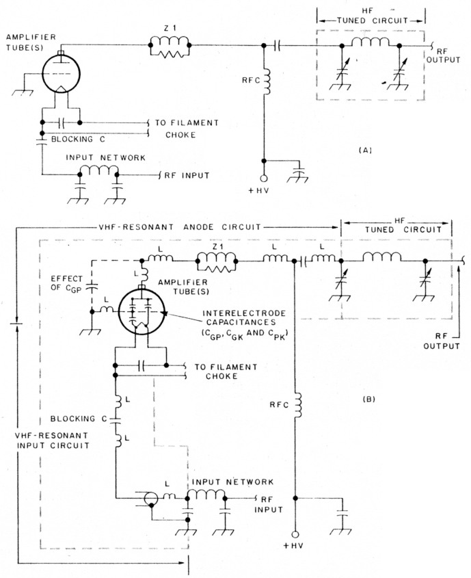
Fig 1 - It's what the schematic doesn't show that sets the stage for parasitic oscillations in a vacuum-tube amplifier. The circuit at A - a portion of a grounded-grid HF amplifiershows just what you'd expect: an input network, tube(s), parallel anode feed and i--network output. The circuit at B shows what you probably wouldn't expect: In conjunction with tube interelectrode capacitances, the inductance (L) of the leads between amplifier components results in VHF resonances in the amplifier's input and output circuitry. (Tube interelectrode capacitances include Cop [grid to plate (anode)], CoK [grid to cathode] and CPK [plate to cathode].) Under some conditions, these resonances, in conjunction with feedback supplied by feedthrough capacitance CpK, can allow the amplifier tube(s) to oscillate at VHF. Z1, a traditional parasitic-suppression network, is intended to prevent such oscillation, but may fail to do so. The text explains why.
VHF parasitic oscillation can occur if (1) the parasitic VHF circuits resonate at or near the same frequency; (2) the parasitic circuits possess sufficient Q at this frequency to sustain oscillation; (3) the amplifier tube(s) are capable of sufficient gain at the frequency at which the parasitic circuits are resonant; and (4) sufficient positive feedback exists at this frequency. VHF energy need not be present in the driving signal to get the parasitic started: If shock excitation of the VHF self-resonant circuits by switching or driving-signal transients doesn't make the amplifier "take off," the normal random variations in the tube electron - stream can suffice. Once started, the oscillation builds until its amplitude is limited by tube characteristics, self-bias or - especially in high-power circuits - component failure. Because the oscillating tube operates without a load at VHF, component failure is likely to be the limiting factor. (Note: It may come as a surprise to some hams that an MF/HF grounded-grid amplifier can betray its user by oscillating as a tuned-plate, tuned-cathode oscillator at VHF. After all, isn't grounded-grid's "no neutralization required" characteristic the reason for the popularity of this amplifier configuration at MF and HF? See the sidebar, "Grounded-grid amplifiers can oscillate" to unravel this conundrum.)
Grounded-grid amplifiers can oscillate
In a grid-driven, grounded-cathode amplifier, the input and output voltages are 180° out of phase. For regeneration and oscillation to occur in such a circuit, in-phase plate-to-grid feedback must be applied by means of a coupling circuit that subjects the fed-back energy to a 180° phase shift. The grid-to-plate capacitance of a high-gain tube may provide sufficient coupling; tuning the plate circuit of a TPTG amplifier to a frequency higher than the grid circuit can place this fed-back energy in phase at the grid. The result is a TPTG oscillator.
By contrast, oscillation may be easier to achieve in a grounded-grid stage than a grounded-cathode stage. After all, the output (anode) and input (cathode) voltages are already in phase in a grounded-grid amplifier - a phase-shift circuit may not be required to achieve the correct phase relationship between the plate and cathode signals. Why doesn't a grounded-grid stage "take off" and oscillate like an unneutralized grounded-cathode stage? Many hams know the answer by heart: "Because the grounded grid acts as an effective shield between the cathode and plate, preventing regeneration and oscillation."
This presumption is true only at frequencies below the grounded grid's self-resonance frequency. Grid self-resonance is unavoidable: At some frequency, the inductances of the grid structure, internal and external leads, and the tube socket resonate with the capacitance of the grid structure. (For example, the grid of a 3-500Z triode, directly grounded, self resonates at about 95 MHz.) At frequencies above grid self-resonance, the grid exhibits inductive reactance and is no longer grounded.
Above its self-resonance frequency, the grid cannot serve as an effective shield between plate and cathode. To make matters worse, the reactance of the tube's plate-to-cathode (feedthrough) capacitance decreases with frequency. Result: As frequency rises above a tube's grid-self-resonance point, the grounded grid becomes progressively "less grounded" and the feedback path between anode and cathode becomes increasingly conductive to RF current - a highly undesirable condition unless the amplifier designer intends to build a VHF oscillator!
Enter the traditional parasitic suppressor
In ham folklore, the traditional LR parasitic suppressor (Z1 in Figs 1A and 1B) puts the double whammy on VHF parasitics by providing two paths for VHF current in the anode lead. The inductor usually consists of several turns of copper wire, tubing or strap, sometimes silver plated. The resistor is usually a noninductive, carbon-composition unit with a power rating of several watts. The explanation of the function of these components varies with the radio witch doctor you consult, but usually goes something like this: The inductor tunes the anode lead to a frequency different from (lower than) what it is without the coil; this helps kill the parasitic by tuning the anode circuit away from wherever it would have been. The resultant stagger tuning of the input and output parasitic-supporting circuits kills the parasitic. Any parasitic energy that remains is forced (by the choke action of the inductor) to flow through the resistor, swamping the parasitic.(6) (The resistor is also supposed to lower the Q of the inductor.) The desired amplifier output signal doesn't cook the resistor because the suppressor inductor offers a low-impedance path around the resistor in the MF/HF range.
All of this looks good on paper, but it is not 100% true. What should you do if this traditional anti-parasitic prescription fails? Here are the curative incantations: "Increase the inductance of the suppressor inductor." "Use a resistor of a different value." "Lengthen or shorten wires in the input or output circuits." "Reposition (a) the a-network tuning capacitor; (b) something; (c) anything; (d) everything." (Varying - especially shortening - lead lengths can improve stability if the new lead lengths move the cathode- and anode-circuit self-resonant frequencies farther apart. This anti-parasitic technique was mentioned on pages 116 and 117 of ARRL's 1935 Radio Amateur's Handbook - good advice then and now. Depending on the amplifier configuration [grounded cathode, grounded grid, grounded anode] in use, parasitic suppression can also be applied in the amplifier grid, screen and/or cathode circuits. See the sidebar, "Parasitic Suppression at the Grid and Cathode.")
One or more of these solutions may do the trick - after a frustrating struggle. Typically, success with a traditional anode parasitic suppressor boils down to increasing the inductance in the tube anode lead until the suppressor resistor almost burns up on 10, 12 and 15 meters. (This "solution" sometimes isn't much of a solution: I know of hams who've resigned themselves to replacing slow-cooked suppressor resistors every few months!) Clearly, the traditional LR parasitic suppressor is a hit-or-miss solution at best. But why?
The answer came to me as I was investigating a severe case of VHF parasitics in a two-3-500Z amplifier - a veritable Pandora's box of parasitics because its 3-500Zs had unusually high gain. (I had already installed cathode parasitic-suppression resistors in this amplifier as explained in "Parasitic Suppression at the Grid and Cathode." The resistors had improved stability, but the amplifier was not unconditionally stable.) Using a dip meter, I discovered that the amplifier's anode circuit exhibited a sharp dip at 130 MHz - even though the anode lead included a traditional, supposedly Q-killing, LR parasitic suppressor! What could be allowing this high-Q resonance to survive?
Anti-Parasitic yechniques and Q
The old adage that "more is not always better" is particularly apt where amplifiercomponent Q is concerned. In a well-engineered MF/HF amplifier, each part of the circuit should possess the appropriate, not necessarily the maximum, Q. In a practical grounded-grid MF/HF amplifier, MF/HF tuned-circuit components should have a high MF/HF Q, and anode leads - including anode parasitic-suppression networks - should have low VHF Q.(7)
One way to lower Q is to simply use low-Q inductors. Copper wire, tubing or strap is the wrong material to use if you're after low Q. Silver plating is the wrong thing to add to copper if you're after low Q. A copper, or silver-plated copper, parasitic-suppression inductor might more accurately be called a parasitic supporter. Yet, silver-plated copper is commonly used for anode-circuit wiring and VHF-parasiticsuppression inductors in vacuum-tube amplifiers - including the two-3-500Z amplifier on my bench!
Parasitic suppression at the grid and cathode
Efforts at parasitic suppression need not be confined to the anode circuit of a grounded-grid amplifier. Stability can also be improved by tuning out some of the inductive reactance in the grid structure with low-value capacitors (connected from grid to chassis.) This raises the grid's self-resonant frequency to a region where - hopefully - the amplifier tube does not have enough gain to oscillate.
Grid-inductance-canceling capacitors are most effective with tubes of older design (like the 811A) that have a considerable grid inductance. This technique is only mildly effective at improving stability with modern amplifier tubes that were designed to have inherently low grid inductance.
Another anti-parasitic technique I discussed in an April 1986 ham radio articlet is the use of a resistor to lower the Q of the input (cathode) lead. (See Fig A). Input parasitic-suppression resistors also reduce intermodulation distortion at the expense of making the amplifier require a bit more driving power.
Input parasitic-suppression resistors are moderately effective at stabilizing unruly amplifiers, but they are not 100% effective. After my April 1986 article was published, about 5% of the reader letters and phone calls I received came from people who reported that their amplifiers were more stable with input parasitic-suppression resistors than without, but still not perfectly free of occasional signs of instability (minor arcing and spitting at the output-network tuning capacitor and/or band switch). I didn't know it at the time, but low-Q anode parasitic-suppressors would be the next - and final - step in getting rid of those parasitics for good.
* R. Measures, "Grounded-Grid Amplifier Parasitics," ham radio, Apr 1986, pp 31-34.
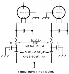
Fig A - Input parasitic-suppression resistors can help to tame VHF parasitics in a grounded-grid amplifier. They also slightly improve the amplifier's IMD performance and make the amplifier a bit harder to drive. See text.
The optional capacitors, C, may enhance the suppression effect of the resistors by providing a more direct path to ground at VHF than that afforded by the amplifier input network. If you install them, be sure to figure their capacitance into the total output capacitance of the input network.
I ascribed much of the inductance responsible for the 130-MHz anode-circuit resonance in the parasitic-ridden amplifier to a 2-inch-long, U-shaped piece of no. 12 copper wire connecting the amplifier's HV blocking capacitor and anode RF choke. I also suspected the silver-plated copper strap used in the amplifier's anode wiring and parasitic-suppressor inductors of contributing to the sharpness of the 130-MHz dip. Replacing these components with their low VHF-Q counterparts was the next step.
Low-Q conductors
Nichrome (nickel-chromium alloy) ribbon or wire has about 1/60 the VHF Q of copper and is a good choice of material for low-Q wiring and inductors. Unfortunately, though, nichrome wire - and especially flexible nichrome ribbon - is expensive and hard to find in small quantities. (As a service to fellow parasitic-tamers, nichrome ribbon and wire is available from me in small quantities. See Appendix 1.) Stainless steel has less than 1/10 the VHF Q of copper and is commonly available.
Trying out the low-Q conductor idea
With nichrome ribbon and stainless-steel wire in hand, I went to work. I replaced the 2-inch piece of no. 12 copper wire - between the HV blocking capacitor and the top of the anode RF choke - with a strip of nichrome ribbon about 1/8 inch wide and 1-3/16 inches long. Next, I wound a three-turn, 1/4-inch-diameter coil of no. 18 stainless-steel wire and connected this coil in parallel with the nichrome ribbon to stagger tune the parasitic-supporting circuit. (See Fig 2.) A dip meter check revealed that the anode self-resonance had moved from 130 to 155 MHz - a desirable change because the 3-5007,s' gain drops with frequency above 110 MHz. Also, the 155-MHz dip was shallower than the dip I'd observed at 130 MHz. So far, so good!
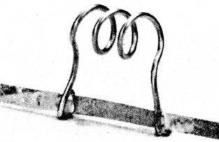
Fig 2 - This low-Q parasitic-suppression network consists of 1/8-inch-wide nichrome ribbon in parallel with a three-turn coil wound from no. 18 nichrome wire. This assembly was used to replace a U-shaped piece of no. 12 copper wire in the anode circuit of a two-3-500Z amplifier. The full parasitic cure also required the installation of cathode-lead resistors and anode-lead LR suppressors. See text and the sidebar, "Parasitic Suppression at the Grid and cathode"
Next, I replaced each of the amplifier's two high-Q, LR parasitic-suppression networks with low-Q networks. Each of the low-Q suppressors consisted of two 100-0, 2-W metal-film resistors in parallel, shunted by a coil made of three turns of no. 18 stainless-steel wire about % inch long and with an inner diameter of 9/32 inch. (A 7-mm or 9/32-inch drill bit works well as a winding form. Nichrome wire or strap can be used for even lower Q; see Appendix 1.) To keep the circuit Q as low as possible, I also used no. 18 stainless-steel wire for the parasitic-suppression-network pigtails. I bent the pigtail ends into circles to allow the new suppression networks to be mounted with the same screws that held the original networks in place.
Results
The once-unruly grounded-grid amplifier shows no signs of instability after anode circuit modification with low-Q inductors - even with all of its cabinet screws in place!(8) The power output appeared to be unchanged, although it is probably about 5 W less at 29 MHz (the worst case) with the low-Q parasitic suppressors installed.
Cathode parasitic-suppression resistors had improved the stability of the amplifier, but eliminating the parasitics required the removal of parasitic supporters - the traditional high-Q LR parasitic suppressors and other conductors in the amplifier anode circuit - and their replacement with low-Q LR suppressors.
Conclusion
High-Q inductors such as silver and copper are the best choice for anode-circuit conductors in a VHF amplifier or VHF oscillator. Low-Q conductors, such as stainless steel and nichrome, are the best materials for all anode-circuit conductors in an MF/HF amplifier. Copper is the best choice for conductors in MF/HF tuned circuits.
The high-Q LR parasitic suppressors traditionally used by hams - and by manufacturers who base their equipment designs on Amateur Radio practice - have been rendered obsolete by improvements in the gain and power bandwidth of high-power vacuum tubes since traditional parasitic-suppression techniques were developed in the 1930s. The parasitic-oscillation problems that have occurred and continue to occur in many Amateur Radio amplifiers - commercial and home-built can be traced to the use of LR parasitic-suppression networks and anode-circuit conductors that actually serve as parasitic supporters. Replacement of these components with suitable low-Q conductors and LR networks can get rid of parasitic problems once and for all - or at least until the next quantum improvement in the gain and power bandwidth of high-power vacuum tubes! If you would like to discuss any part of this article or the parasitic-oscillation malady in general, please feel free to telephone me at 805-482-3034.
Danger - High voltage!
Working with vacuum-tube amplifiers involves voltages and currents that can kill you instantly should you come into contact with them. Take proper safety precautions whenever you work on such equipment. Before working on an amplifier:
- Turn off the amplifier.
- Unplug the amplfier from the ac line.
- Wait until the HV meter indicates less than 100 V.
- Using a shorting stick in series with a 100-0, 25-W resistor, short the amplifier B + to ground to discharge the HV-supply filter capacitors. (The resistor protects the amplifier's anode- and grid-current meters (and the meters' shunt resistors, if any) from damage as the capacitors are discharged by the shorting stick.)
Pulling the plug and following these steps is the only safe way to work on an amplifier. Most interlocks do not disconnect the line voltage from the amplifier when the amplifier lid is removed.
Notes
(continued on page 89)
AG6K, Richard L. Measures.