Home - Techniek - Electronica - Radiotechniek - Radio amateur bladen - QST - Calculating power dissipation in parasitic-suppressor resistors
Sure, the resistors in VHF-parasitic-suppression networks dissipate some HF energy, especially on 10 meters. But how much? The answer may surprise you!
How much MF/HF power is dissipated in the resistors used in LR (inductor and resistor) VHFparasitic-suppression networks in tube-based MF/HF amplifiers? Apparently, most amplifier builders choose the power rating of these resistors empirically: "If it burns up, try something different." A more scientific engineering method might be useful!
The calculation of suppressor-resistor dissipation involves three major steps and a number of minor steps. The first major step is to find the maximum RF current that flows through the anode parasitic-suppression network (assumed to be aparallel LR circuit). The second major step involves finding the voltage drop across this parallel LR circuit. The third major step is to calculate the power dissipated in the resistor on the basis of the MF/HF voltage across it.(1)
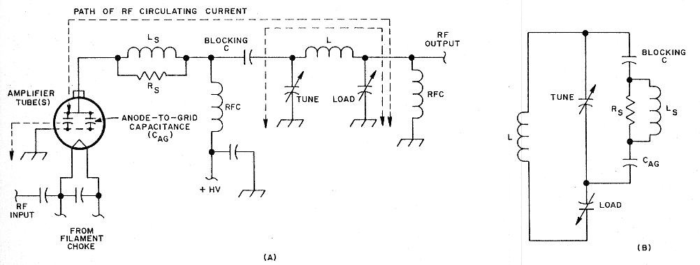
Fig 1 - In a grounded-grid amplifier, the anode-to-grid capacitance (CAG) of the amplifier tube(s) carries part of the output-network RF circulating current, as shown at A. Assuming that the amplifier is operated at the same power level throughout its frequency range, the RF current through CAG is greatest at the highest frequency in that range because the reactance of CAG decreases with frequency. Whatever circulating current flows through CAG also flows through the VHF-parasitic-suppression network (LSRS) because this network is in series with CAG. Redrawing the output network as a parallel tuned circuit (B) makes this series relationship more apparent.
Power dissipation in the suppressor resistor is greatest during operation on the 10-meter band. This is because more of the amplifier-output-network circulating current flows through the amplifier-tube output capacitance (anode-to-grid capacitance [CAG] in a grounded-grid amplifier) on 10meters than on lower-frequency bands. See Fig 1A.
The reason for this is that capacitive reactance decreases as frequency increases. At the upper end of the 10-m band (29.7 MHz), the output capacitance of the amplifier tube(s) exhibits less reactance than at all frequencies lower than 29.7 MHz. Because the ac anode voltage - which is impressed across CAG - is constant from band to band (assuming that the amplifier is operated at the same output power on all bands), the alternating current that flows through CAG is maximum at 29.7 MHz. Once the ac anode voltage is known, the current through CAG can be calculated by using a variation of Ohm's Law.
As Fig 1B illustrates, the anode parasitic suppressor (LSRS) is in series with CAG. Because of this, whatever RF current flows through CAG also flows through LSRS. Once we know the magnitude of the RF current through CAG, we'll know how much current flows through the LSRS network. This information, in conjunction with the impedance of LSRS, will allow us to calculate the RF voltage drop across LSRS, and, therefore, the RF voltage drop across RS.
Calculating the AC Anode Voltage
The peak ac anode voltage depends on several factors: the dc anode voltage, the grid voltage with respect to ground, and whether or not the amplifier is properly tuned. (For more on how amplifier tuning affects peak ac anode voltage, see the sidebar, "Why Proper Amplifier Tuning is Important.") Assuming that the amplifier is properly tuned, the peak change in anode voltage is equal to the dc supply voltage minus about 200 to 300 V. (Using the lower number results in a more conservative suppressor-resistor-dissipation estimate.)(2) This peak voltage can be converted to its root-mean-square (RMS) value by dividing it by ![]() (approximately 1.414).(3)
(approximately 1.414).(3)
At this point, we can begin working a sample problem. A hypothetical MF/HF amplifier contains a 3-500Z triode (CAG = 4.7 pF) operating in grounded grid at a dc anode supply of 4 kV. Its anode parasitic-suppression network consists of a 0.05 µH inductor in parallel with a 25-Ω resistor. From the foregoing discussion, we calculate that the peak change in anode voltage is 4000 V - 200 V, or 3800 V. To find the RMS equivalent of this voltage, we divide 3800 by 1.414. Answer: The 3-500Z in the hypothetical amplifier operates at an RMS anode potential of 2.687 kV.
Calculating the Reactance of CAG
We can find the reactance of CAG with the capacitive reactance formula (Xc = 1 ÷ 2ΠfC). Applying this to our sample problem: The 3-500Z's anode-to-grid capacitance is 4.7 pF; at 29.7 MHz, XCAG is -j1140 Ω.
Calculating the RF Current Through XCAG
Ohm's Law serves here. Substituting XC for R, the RF current through CAG can 'be found with the formula I = E XCAG, where I is the RF current in amperes and E is the RMS anode voltage.
Based on an anode potential of 2.687 kV RMS, the RF current through CAG of a 3-500Z (4.7 pF) is 2.36 A RMS at 29.7 MHz. Because the parasitic-suppression network (LSRS) and CAG are in series, the RF current through LSRS is also 2.36 A RMS at 29.7 MHz.
Calculating the Suppressor-Network Impedance
Because the suppressor-network components are connected in parallel, the RF voltage drop across Rs is equal to that across LSRS. To calculate this voltage drop, we must first calculate the network impedance.
LSRS exhibits a complex impedance because it consists of reactance (XLS) and resistance (R). The presence of reactance makes finding the network impedance a bit more complicated than solving a simple parallel-resistance problem.
Two approaches can be used to find the impedance of LsRs; which approach you use depends on whether you prefer to think in terms of impedance or its reciprocal, admittance. The sidebar, "Finding Impedance by Solving for Admittance," explains the admittance approach.(4) For those who prefer to work with impedance, the impedance of LSRS can be found with the equation
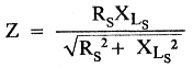
where
Z = network impedance in ohms
Rs = resistance of Rs in ohms
XLS = reactance of LS in ohms
Returning to our sample problem: The suppressor network in the anode of the 3-500Z consists of a 0.05-µH inductor in parallel with a 25 Ω resistor. XLS can be found with the inductive reactance formula (XL = 2ΠfL); in this case, XLS is equal to j9.3305 Ω at 29.7 MHz. Solved with RS = 25 Ω and XL = 9.3305 Ω, Eq 1 reveals a network Z of 8.74 Ω at 29.7 MHz.
Calculating the RMS RF Voltage Across the Network
Finding the voltage across the network requires only the application of Ohm's Law (in this case, E = IZ, where I is the network current (2.36 A) and Z is the network impedance (8.74 Ω). Answer: At 29.7 MHz, the RMS voltage across our hypothetical LR parasitic-suppressor network is 20.6.
Calculating the Power Dissipated in RS
Now that we know the voltage drop across the network (and, hence, across RS), we can calculate the power dissipated in RS with the equation P = E2 ÷ RS, where P = power in watts, E = the RMS voltage drop across RS, and RS = resistance of RS in ohms.
Concluding our sample problem: A drop of 20.6 V RMS across Rs (25 Ω) indicates that RS dissipates 17 W at 29.7 MHz.
Finer Points
RS dissipates 17 W as a result of the sinusoidal RF circulating current that passes through the 3-500Z anode lead and the parasitic-suppression network. An additional, lesser current flows through the anode lead and suppressor during the 180 ° (or so) of downward anode-voltage swing that occurs when the tube conducts. These pulses occur at the amplifier operating frequency - 29.7 MHz in the sample problem. This additional current causes a half-wave, RF-pulse voltage drop across RS that adds, on the bottom half of the cycle, to the RS voltage drop due to sine-wave circulating current. This increases the total power dissipated in RS.
The fact that this waveform is a halfwave RF pulse instead of a sinusoid complicates the math necessary to find the additional power dissipation caused by this current. An accurate mathematical analysis would require the generation of a formula that accurately describes a waveform consisting of the half-wave RF pulse plus the sinusoidal circulating-current waveform. Calculus could then be employed to more closely calculate the RMS power actually dissipated in RS. Such analysis is beyond the scope of this article.
It is somewhat easier to use this approximation: In a typical amplifier, the half-wave anode-current pulse increases the power dissipated in RS by about 15% over that due to RF circulating current. Thus, in our sample problem, the total power dissipated in RS is 1.15 × 17 W, or 20 W.
Practical Notes
Twenty watts represents, to me at least, a surprising amount of HF power dissipation in a fairly low-inductance LR parasitic suppressor. (Although the network inductance in the sample problem was 0.05 µH, most of the parasitic suppressors I've seen contain more inductance than this. The resistors in such networks probably dissipate more power than what we've calculated here.)
Of course, the sample problem represents a worst-case scenario of 29.7-MHz "lock-to-talk" RTTY or FM operation at full power. Many radio amateurs use their amplifiers at reduced anode voltage during RTTY and FM operation, however; the parasitic-suppression resistors in these amplifiers are probably not subjected to more than half of the 20-W maximum dissipation calculated in the sample problem. SSB operation, during which amplifier tubes operate at a duty cycle of about 15% with normal human voices, subjects Rs to about 3 watts of average dissipation at 29.7 MHz. This partially explains why the typical parasitic-suppressor assembly survives even though it contains only two or three 2-W resistors.
Another factor in the survival of seemingly underengineered suppressor networks is that modern metal-film and metal-oxidefilm "flameproof" resistors are very rugged: They are not as easily turned into "crispy critters" as were the heat-intolerant, phenolic-cased, carbon-composition resistors of yesteryear. (I have tested modern, 2-W [rated at 70 °C ambient], metal-and metal oxide-film resistors that can dissipate 5 watts each in free air for 1 hour with no apparent changes. These amazing resistors can dissipate 20 watts each for at least 6 seconds with no permanent change in appearance or electrical characteristics.)
An amplifier tube that exhibits more than the 4.7 pF of CAG exhibited by the 3-500Z in our sample problem will subject a parasitic-suppression network to substantially more RF circulating current than the 2.36 A in the sample problem. The resultant higher RMS voltage drop across Rs increases dissipation exponentially (remember, the voltage term is squared in P = E2 ÷ R!). For example, an 8877 has 10 pF of CAG - more than double the capacitance of a 3-500Z. This means that, for the same anode voltage and LR values used in the example, the 8877's anode circulating current more than doubles (to about 5 A RMS)-more than doubling the voltage drop across RS. Because voltage is squared in the power equation, the power dissipated by RS would increase by a factor of greater than 4 to more than 80 W at 29.7 MHz!
Finding the optimum inductance for LS is a tricky balancing act.(5) An inductance small enough to keep RS from roasting on 10 meters may not necessarily be enough to prevent VHF parasitic oscillation, especially if the suppressor inductor is made of (high-Q) copper (or, worse yet, silver-plated copper) instead of low-Q nichrome or similar resistance wire.
One solution to the suppressor-dissipation problem is to use a large, noninductive, Globar resistor for RS.(6) Unfortunately, Globar resistors are expensive. A more cost-effective solution is to use two (or more) small LR parasitic suppressors, built around inexpensive 2-W metal-film resistors, in series. For an amplifier tube that has a CAG of 20 pF or more, it's easier to build a long-lived LR parasitic suppressor using heat-tolerant nichrome wire or ribbon for LS and RS than it is to build a suppressor based on a conventional resistor.
Summary
The resistors used in anode LR VHF parasitic-suppression networks dissipate considerable quantities of HF power, especially at the upper end of the HF range. This power dissipation can be calculated with sufficient accuracy to allow specification of Rs wattage by design rather thanby guess. If you would like to discuss any part of this article with me, call me at 805-482-3034.Notes
- Power dissipation in the suppressor resistor due to do anode current is negligible because the resistor is bypassed for dc by the suppressor inductor.
- The minimum-anode-voltage requirement of amplifier tubes is generally related to power-handling capability: Higher-power tubes generally have higher minimum anode-voltage requirements than lower-power, tower-voltage tubes.
- This relationship is true only for pure sine waves; the relationship between peak and RMS voltages is more complex for nonsinusoidal waveforms. For the purposes of this discussion, it's acceptable to assume that the RF waveform at the anode(s) of a vacuum-tube, linear RF amplifier is sinusoidal. The concept of RMS voltage is valuable to us because it allows direct comparison of the heating effects of dc and ac. The heating caused by a drop of 1 V RMS across a given resistor is equivalent to the heating caused by a drop of 1 V dc across the same resistor. -Ed.
- It can be argued that the relationship between current and voltage in a parallel-LR network is better analyzed in terms of admittance because an admittance diagram (Fig A in the sidebar) can be drawn for combinations of parallel L, R and C, but an impedance diagram cannot. Despite this, however, either concept-impedance or admittance-may be successfully (and simply) applied to finding the power dissipated by RS. Thus, we present the application of both concepts for the reader's convenience. The simple, reciprocal impedance/admittance conversions discussed in the sidebar are unrelated to finding the series equivalent of a parallel circuit or the parallel equivalent of a series circuit; such transformations offer no shortcuts in finding the power dissipated in Rs. "Finding Impedance by Solving for Admittance" discusses conversion of the parallel reactance and resistance of L R to parallel susceptance and conductance (BsGs) so that an admittance diagram can be drawn. -Ed.
- "Richard Measures" technique for measuring the inductance of the suppressor inductor will appear in a forthcoming Hints and Kinks column. -Ed.
- A friend of mine uses a 50-W Globar resistor for Rs in his large amplifier; the resistor gets very hot during key-down testing at 29 MHz. This resistor has never burned out, but it has glowed dull red a few times during a parasitic oscillation near 68 MHz!
Why Proper Amplifier Tuning is Important
A grounded-grid linear amplifier should be tuned so that most of the electrons emitted by the cathode reach the anode circuit. Electrons that fail to reach the anode are lost to grid current. This condition occurs when the amplifier is loaded too lightly-the result of setting the loading capacitor for too much capacitance during tune-up. As grid current rises and fewer electrons reach the anode, distortion increases and output power decreases. Thus, a triode amplifier can be tuned up with fair accuracy by simply applying maximum drive power and quickly adjusting the amplifier's TUNE and LOAD controls for maximum power output.(a)
Electrons are negatively charged. Positive charges attract them. The more positive the charge, the stronger the attraction. The 0-V potential of a grounded control grid is more positive than the negative charge of a electron leaving the cathode of a vacuum tube. This causes excessive current to flow in the control-grid circuit unless the tube anode is substantially more positive than the control grid throughout the anode-voltage cycle.
The output of a grounded-grid RF amplifier tube appears at the tube anode as RF ac superimposed on the dc anode supply. As a rule of thumb, successful attraction of most of the cathode's electrons requires that the instantaneous anode voltage not fall below about +200 to +300 V (relativa to the grounded grid) during the lowest point of its downward voltage swing (that is, during the anode-current peak). Loading the amplifier too lightly-that is, adjusting the amplifier LOAD control for too much loading capacitance-causes the minimum anode voltage to fall below this level. The result is a dramatic increase in grid current and distortion, and a reduction in peak power output. Loading the amplifier too heavily-insufficient loading capacitance-also causes the output power to decrease because the amplifier output network is not adjusted to the impedance-transformation ratio necessary for maximum power transfer between the amplifier and its load.
AG6K, Richard L. Measures
- After the amplifier has been tuned for maximum output, a slight increase in linearity can usually be secured by increasing the amplifier loading-that is, by decreasing the loading capacitance-until output power decreases by a few percent. Note, however, that this small improvement in linearity is seldom detectable in practice because the IMD performance of tube amplifiers is usually significantly better than the IMD performance of the bipolar-transistor-output transceivers commonly used nowadays as exciters.
Finding Impedance by Solving for Admittance
More radio amateurs seem to be familiar with series LRC circuits and impedance in units of ohms than with parallel LRC circuits and admittance in unite of siemens (S, equal to 1/Z). Impedance (Z) describes the ability of a circuit to resist the flow of ac. Admittance (Y, equal to 1/Z) describes the ability of a circuit to conduct the flow of ac. Whether you decide to evaluate a circuit in terms of resistance or conductance is akin to deciding whether A container is half full or half empty. Both viewpoints are valid, but one approach may be more useful than the other, depending on the nature of the circuit (or the function of the container).
The concept of impedance is more useful than admittance in work with series circuits, in which the current is uniform in all elements and the voltage across all elements is different. Admittance is more useful than resistance in work with parallel circuits, in which the voltage across all elements is uniform and the current in all elements is different.
In the, relatively well-known realm of impedance, capacitive reactances (XC) are expressed in units of negative ohms because voltage across the capacitor lags the current through the capacitor by 90° of the waveform applied to the capacitor. Inductive reactances (XL) are expressed in units of positive ohms because, in an inductor, the voltage across the inductor leads the current through the inductor by 90° of the waveform applied to the inductor.
In the reciprocal world of admittance, the reactance polarity signs reverse, and reactance (X) undergoes a name change to susceptance (B). For example, a capacitor that exhibits a capacitive reactance (XC) of -3Ω at a given frequency exhibits +1/3 S of capacitive susceptance (BC, equal to 1/XC) at that frequency.(b)(These values can also be written as XC = -J3 Ω and BC = +j1/3 S, respectively. The j indicates [for purists] that the reactance/susceptance values are imaginary - in ,this case, they are multiplied by the square root of -1 - but the presence of j can be inferred whenever reactive [X] or susceptive [B] values are present in an equation.) Inductive susceptance (BL) is equal to 1/XL.
Why consider a parallel LR circuit in terms of admittance rather than impedance? The formula for the impedance of parallel reactance and resistance (see Eq 1 of the main text) may scare away people who are otherwise comfortable with the formula for the impedance of series reactance and resistance ![]() . By converting the reactance in a parallel circuit to susceptance, and the resistance in the same parallel circuit to conductance, you can use the series impedance formula to find the impedance of a parallel RX circuit merely by solving the equation and dividing 1 by the resulting admittance (Y). As Fig A shows, this is easier. done than said!
. By converting the reactance in a parallel circuit to susceptance, and the resistance in the same parallel circuit to conductance, you can use the series impedance formula to find the impedance of a parallel RX circuit merely by solving the equation and dividing 1 by the resulting admittance (Y). As Fig A shows, this is easier. done than said!
I have found that it's easier for me to keep things. straight in a parallel-circuit problem if all conductance, susceptance, and admittance values are written as 1/ohms (S). (This technique also speeds. converting conductance, susceptance, and admittance values to the more familiar ohm values: Merely invert the 1/ fractions and replace S with Ω.) For me, a conductance of 0.008333 S is easier to visualize if it's expressed as 1/120 S; either way, it's still a brown-red-brown (120Ω) resistor! -Richard L. Measures, AG6K
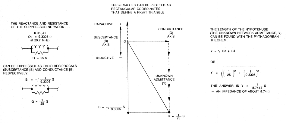
Fig A - The impedance of a parallel RX circuit can be calculated with a variation on the familiar series AX impedance formula by using the reciprocals of resistance (R) and reactance (X) (conductance [G] and susceptance [B), respectively) in the series formula. The result is the admittance (Y) of the parallel circuit; the impedance of the circuit equals 1/Y. This example also reminds us that the familiar formula for Z of series RX (and Y of parallel GB) is based on the Pythagorean theorem. In both cases, we're working with vector quantities to solve for the hypotenuse of a right triangle. (For more information on working with complex impendances, see Chapter 2 of The ARRL Handbook and Chapter 5 of The ARRL Extra Class License Manual.)
AG6K, Richard L. Measures.