Home - Techniek - Electronica - Radiotechniek - Radio amateur bladen - QST - A simple secondary frequency standard
This simple weekend project nets you an accurate frequency standard and a dedicated WWV receiver.
One FCC requirement that has not changed in this era of deregulation is your need to observe the frequency limits of each amateur band and the limits of the subbands for your license class. Today's transceivers have built-in calibrators, but these calibrators have limitations: Some are awkward to use, and all need to be checked periodically against an accurate frequency standard, such as WWV.
The US National Institute of Standards and Technology (formerly National Bureau of Standards) stations WWV and WWVH transmit accurate frequency and time signals on 2.5, 5, 10, 15 and 20 MHz. Using an atomic standard as the primary reference, these signals have an accuracy of 1 part in 1011 - 1 Hz in 100 GHz. We hams don't need this level of accuracy, but we can approach 1 part in 107 (1 Hz in 10 MHz) without undue strain on technology or budget. The secondary frequency standardldescribed here provides such accuracy inexpensively and gives you a receiver for WWV time checks and propagation information as well.
The Circuit
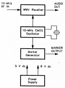
Fig 1-Block diagram of the Simple Secondary Frequency Standard.
My standard uses the Neophyte receiver described by John Dillon, WA3RNC, in February 1988 QST(2) along with some common ICs for marker generation. Fig 1 shows a block diagram of the standard. I recommend that you refer to Dillon's article; it contains a lot of detail about the receiver that won't be repeated here.
The Neophyte, a direct-conversion (DC) receiver, was originally designed for 80-and 40-meter operation. I've converted it to a 10-MHz WWV receiver by adding a 10-MHz CMOS local oscillator (LO) and retuning its front end. The 10-MHz oscil lator is also divided by the TTL string to give 1-MHz, 100-kHz, 50-kHz and 25-kHz markers.
D-C receivers have been popular over the years, and rightly so. Sometimes referred to as "zero-IF" receivers, they use an LO signal at (or, for CW, very close to) the received-signal frequency. Although normally used for CW and SSII reception, DC receivers can copy AM signals when they are tuned to exact zero beat with the signal carrier.
The standard uses analog and digital circuits, and the two must be interconnected. The 10-MHz LO circuit is the best place to do this. Initially, I tried crystal-controlling the Neophyte 1.0, but the LO output was insufficient to drive the markergenerator TTL string. I tried several simple LO amplifiers with mixed success. Realizing that the interface circuitry was more complicated than it needed to be, I decided to drive the Neophyte with an external L.O.
The external LO used in this application must meet several requirements. It must be lightly loaded for good stability, consume little power, be capable of providing 200 to 300 mV of drive to the Neophyte, and yet still be able to drive a TTL load. A single CMOS chip-the CD4049A-provides all these requirements with a minimum of parts. The CD4049A, a hex inverter/buffer, makes an excellent oscillator, can drive two standard TTL loads, consumes little power and is inexpensive.
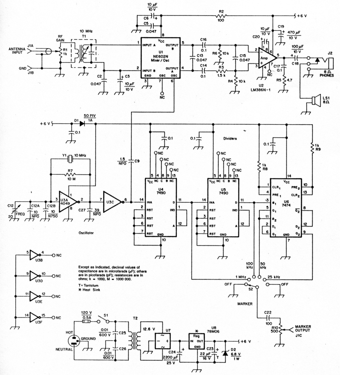
Fig 2 - Schematic of the Simple Secondary Frequency Standard. Unless otherwise noted, capacitors are 50-V monolithic or disc-ceramic units. Polarized capacitors are electrolytic. Fixed resistors are 1/4-W carbon-film units unless noted.
Fig 2 is a schematic of the Neophyte, its new LO and the marker generator. Although standard (74 series) TTL chips (114, U5 and 116) are used for the marker generator in the unit shown, the 74LS series can be used if desired. U4 and U5 provide two cascaded divide-by-10 ratios to divide the 10-MHz signal to 1 MHz and 100 kHz. U6, a 7474 dual-D flip-flop, divides the 100-kHz signal to 50 and 25 kHz.
The power supply is straightforward, but you might look askance at the use of a bridge rectifier when a simple half-wave rectifier might do. The bridge used is not costly, and it helps reduce power-supply hum, a potential bugaboo in D-C receivers.
Voltage is regulated by U8, a 78M06 3-terminal, 6-V regulator. If you can't find a 78M06 (TO-5 version), you can use a standard 7806 or a TO-220-cased 78M06, or even an adjustable regulator set to 6 V. Check your wiring; pinouts vary among the different devices. Use a heat sink on U8: It gets quite warm when standard TTL chips are used for U4-U6. D2, a 6.8-V Zener diode, is optional. U3 can safely withstand full power-supply voltage, but J2 and U4-U6 have maximum voltage ratings of 9- and 7-V dc, respectively. D2 is cheap insurance in case of a blown `regulator.
Building the Standard
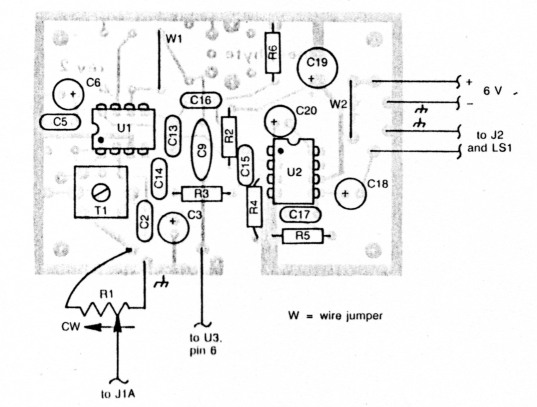
Fig 3 - Parts-placement diagram for the mortified Neophyte PC board. Parts are placed on the non-foil side of the board. The shaded area represents an X-ray view of the copper pattern. Note that there are no modifications to the etching pattern shown in the original Neophyte article; just components change.
The Neophyte PC board is used as is.(3) I've deleted parts, changed some parts values and made wiring changes. The new parts-placement guide is shown in Fig 3. C1, C4A, C4B, C7, C8, C10, C11 and T2 are deleted. C9 is changed to 1.5 pF and installed where C10 was. W1, a jumper, is installed at C9's former location. Dl is moved to the digital board. Another jumper, W2, is installed where Dl used to be. C12, the Neophyte tuning control, is replaced by a 20-pF variable capacitor in parallel with two temperaturecompensating ceramic capacitors (see the sidebar, "Temperature Compensation"). C12, FRFQ, is used to shift the crystal frequency to zero beat with WWV.
The Neophyte is powered by 6 V dc. U3-U6 operate at 5 V dc by virtue of the drop across Dl. The speaker and headphone audio outputs are retained.
Buy a good-quality crystal for Y1. Avoid cheap microprocessor crystals, no matter how tempting their price might be. Y1 should have a frequency tolerance of 0.001% or better (± 100 Hz at 10 MHz). A crystal with a tolerance of 0.0005% is not that much more expensive. The average microprocessor crystal has a tolerance of only 0.01% - 1 kHz at 10 MHz - and some I checked were much worse. Crystal manufacturers such as JAN and International will sell single crystals to amateurs.
I recommend Molex® pins or small sockets for mounting the ICs. If you use Molex pins, first cut them to length, leave the bridging strips attached until you are ready to install the chips. Install the rest of the components on the Neophyte board beginning with T1, the resistors, ceramic capacitors and finally the electrolytics. When you are done, carefully inspect the foil side of the board to make sure that there are no shorts or solder bridges between traces.
The power-supply components, CMOS oscillator and marker generator are on a separate board. I used a Radio Shack® no. 276-170 PC prototyping board. You can use perforated board or wire-wrap techniques with equal success. A detailed layout is available from ARRL HQ for those who'd like to duplicate my technique.(4)
After all components are mounted on each board, install the ICs in their sockets. If you used Molex pins for the sockets, use a pair of needle-nose pliers to gently bend the bridging strips back and forth until they break off cleanly. Make sure the pins are in line and then carefully insert the chips, seating them firmly. U3 has protective diodes across each input, so you should not have any problem with static electricity destroying its input gates.
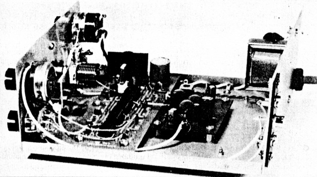
Fig 4 - Interior view of the Simple Secondary Frequency Standard.
I mounted both boards to the cabinet with screws and 1/4-inch-long metal spacers. Be sure to ground each board through solder lugs mounted on the underside of the board at each spacer. Fig 4 shows how I mounted the boards so that the lead lengths between the boards, and to C12, are as short as possible. These are the only critical RF leads.
I used 16 miniature test-point terminals for connections to the hoards. (Terminals are not necessary, but they make interconnection between the boards and the front-panel controls casier.) Two short pieces of no. 22 tinned wire connect C12 to the digital board.
The power transformer is mounted on the left side of the rear panel, and the ANTENNA INPUT/MARKPR OUTPUT terminal strip is on the right side. I installed this particular terminal strip to allow the use of a random-wire antenna; you can use phono or coaxial connectors if you want.
The speaker mounts over louvers on the right rear of the cabinet cover. This keeps the speaker away from the transformer to minimize hum pickup. The PHONES jack is mounted on the front panel for convenience. Shielded wire is used for the leads to T1 and for the audio-output leads from the Neophyte board to the speaker and the headphones. The mar ker-output lead from the output control is also shielded, but the marker leads from the digital board are short enough so that ordinary hook-up wire can be used.
Cl2 mounts on a I x I-5/8 x 1/16-inch aluminum plate. The plate mounts on the 1-inch-long screws that hold the dial to the front panel for maximum rigidity. Note the capacitor mounting position shown in Fig 4. 1 mounted the capacitor this way to minimize lead length to the digital board and to make it easier to attach the lenmpelature-compcnsating capacitors. The use of a vet nier dial may scent unnecessary, but the convenience it provides for zero beating the receiver to WWV or WWVH is worth the cost.
A TO-220 78M06 regulator is available from Mouser. Any small 20- to 25-pF variable capacitor is suitable for Cl2. Some items, such as the vernier dial and the cabinet, vary in price from supplier to supplier, so check around. Note that mailorder suppliers usually have minimum-order requirements. The frequency standard does not require shielding, so a plastic cabinet works as well as the metal one used on the unit shown. Flea markets, hamfests and your buddy's junk box are also good places to buy or barter any parts you may need.
Calibration and Operation
Calibration is easy once you are receiving a good signal from WWV. Don't try to calibrate the standard on a weak or fading signal-accuracy will suffer. Calibration is best done when there are no propagation anomalies.(5)
Set the vernier dial to 50, or midrange on the variable capacitor. Apply power. Assuming all is well, plug in your headphones and advance the RF GAIN control, R1, for a comfortable listening level. You should hear WWV, and the signal can be maximized by tuning Tl to resonance. Use a plastic screwdriver for this adjustment, not a metal one. Once TI is peaked properly, adjust the vernier dial for zero beat.
Wait for the silent period between 45 and 60 seconds of each minute. Although WWV and WWVH broadcast voice announcements for Geophysical Alert Broadcasts with no accompanying audio tones, the main silent periods extend from 45 to 51 minutes after the hour on WWV, and from 15 to 20 minutes after the hour at WWVH. These are ideal times to calibrate the standard.
Adjust the vernier dial. You will hear one or more beat notes depending on how far off the crystal oscillator frequency is. As you approach zero beat, you will hear a fluttering sound followed by a "wowing" sound very close to actual zero beat. By careful adjustment of the control, you should get the wowing sound to less than one beat per second. It may take several silent periods, so be patient. It is also possible to tune to zero beat on the voice announcements just as you would tune in an SSB signal: Simply tune slowly for maximum voice clarity. Adjustment for zero beat can also be done by using WWV's audio tones.(6) Once the crystal calibrated, your starkers will be quite accurate.
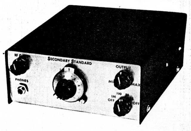
Operation of the standard is the same as with any other marker generator. Couple a small amount of marker output into your receiver or transceiver. Select the marker ftequeucy you want with the MARKER switch, and adjust the marker OUTPUT control for a comfortable level. The RF GAIN control can he used to turn down the audio signal while leaving the markers on. Conversely, you can shut the markers off and leave the Neophyte on.
Stability-Short-Term versus Long-Term
Once you have the crystal zero beat with WW V, your standard's accuracy should be close to 1 Hz in 10 MHz-but what will it be tomorrow? Over the short term-hours to days-the crystal frequency will not hold still. Temperature variations, turning the unit on and off and aging effects cause its frequency to wander about. Crystal aging is a long-term effect that occurs over months and years, and there is little you can do about it. Usually, aging is not severe. It is a function of crystal manufacturing techniques and the crystal drive level. One manufacturer quotes aging rates of 3 to 5 parts per million for the first year, with subsequent aging rates being reduced by 50% to 70% per year.(7)
Short-term stability is of more concern in a standard like this. Temperature variation is the main cause of short-term wandering of the crystal frequency. Anything you can do to reduce or eliminate it will help greatly. You can leave the standard on all the time and keep it in a room where temperature variations are limited. Beyond that, proper selection of the temperature-compensating capacitors (see the sidebar, "Temperature Compensation") is the most important factor in reducing short-term drift.
Other Possibilities
Obviously, the standard is quite useful in the workshop for testing and calibrating other equipment. In addition, you don't have to use 10 MHz if the 2.5- or 5-MHz WWV signal is more consistent at your station. (I doubt that the 15- or 20-MHz signals would be of much use as a standard because of the vagaries of HF propagation.) Chapter 6 of the latest edition of The ARRL, Data Book shows how to wire the 7490s for different division ratios. Remember, you'll have to retune the Neophyte's front end, too.
In the unit shown, the MARKER switch has two OFF positions for the sake of convenience. If you delete one, you could use it to switch the output to a piece of shielded cable to bring out the 10-MHz signal for other uses.
So there you have it-a simple secondary standard that provides very accurate markers and serves as a WWV receiver to boot. It's easy to build and low-cost, considering its accuracy and usefulness.
A Bit About CMOS Oscillators
The secondary frequency standard uses a CMOS oscillator to drive a divider chain, and as the Neophyte receiver's local oscillator (LO). A square-wave oscillator like this may not seem like a good candidate for a receiver LO, but balanced mixers (such as the Gilbert-cell mixer used in the NE602N) work quite well with a square-wave LO. Using a square-wave LO can provide 10 to 15 dB more LO rejection than can normally be achieved with a sine-wave oscillator.
CMOS oscillators are usually built around an inverter chip. Oscillators using an even number of cascaded inverters can be tricky to get running properly, but any odd number of inverters will always oscillate with a suitable frequency-determining feedback network. Fig A shows a diagram of a basic oscillator circuit.
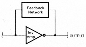
Fig A-Basic oscillator circuit.
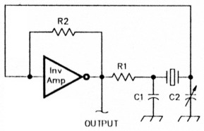
Fig B-Typlcal crystal oscillator circuit using an Inverter.
A crystal makes an ideal feedback network. Fig B shows a typical crystal-oscillator circuit that uses an inverter. R1 and R2 control the feedback and loop attenuation. R2 ensures that the inverter has a dc path from output to input to bias it on. This resistor should be at least 1 megohm; values of 10 to 22 megohms are commonly used to keep the Q of the crystal from being degraded.
Both C1 and C2 affect the oscillator frequency; they are usually made equal in value, with C2 variable to permit fine tuning. Just how much tuning is possible depends on the crystal characteristics and the specific oscillator circuit.
Any odd number of inverters can be used, but propagation delay through the total string affects the highest possible operating frequency. Operating frequency is not the only consideration, however.
Many crystals will oscillate readily at their third overtone. (An overtone is a complex crystal resonance that occurs at a frequency close, but usually not identical, to an odd-numbered harmonic of the crystal's fundamental frequency.) Usually this is undesirable; a simple solution to this problem is to cascade enough inverters-always using an odd number--so that the propagation delay around the loop is too long for the third overtone to be reinforced at the input. The delay must not be so long that fundamental operation is suppressed, however.
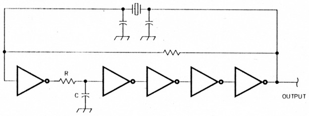
Fig C-One way of suppressing unwanted overtone operation.
Fig C shows a second way of suppressing unwanted overtone operation. The RC combination in Fig C is a low-pass filter which has a cutoff frequency well below the crystal's third overtone (but above the desired oscillator frequency!). This prevents positive feedback at the overtone.
Temperature Compensation
You can temperature-compensate the standard to minimize the effects of temperature variation. You may not always be able to receive a usable signal from WWV, and you need confidence that the standard is not very far off frequency during such times. C12 is a 20-pF variable In parallel with a fixed-value NPO (zero-temperature-coefficient) capacitor (C12A) and a fixed-value N750 negative-temperature-coefficient capacitor (C12B). With C12 sot at midrange-10 pF-the fixed capacitors bring the total to 30 pF. To start with, make the two fixed capacitors equal in value (10 pF each). A simple-but somewhat lengthy - procedure is used to adjust the two capacitor values to reduce the frequency drift with temperature to a minimum. This procedure is similar to one described by Irwin Hoff, W6FFC, in November 1968 QST.(A)
To adjust the temperature-compensating capacitors, turn the standard on and let it run for a few days. When the room is as cold as it normally gets, carefully set the frequency close enough to WWV that you can count the beat note (wows) for a period of 30 seconds or so. Write down the number of beats so you won't forget the value. Then, when the room Is about as hot as It normally gots, come back and count the beats again. If there has been a change, adjust the vernier dial for a low beat count, and again count the beats over a 30-second period.
Note which way you adjusted C12. If you increased the capacitance of C12, the crystal drifted higher and you need to decrease the value of the N750 capacitor-say, to 5 pF. Then increase the NPO capacitor to 15 pF so the total capacitance stays at 30 pF with the vernier dial set at midrange. This means you need a small supply of low-value NPO and N750 capacitors. My unit needed an 8-pF NPO in parallel with a 12-pF N750 for final compensation.
Repeat this procedure the next day and make any further adjustments to the NPO/N750 capacitor combination to further reduce the drift. If you go too far and drift is reversed, simply back up until the drift is eliminated. It shouldn't take more than a couple of days until the drift is reduced to just a couple of hertz. You can use ceramic capacitors with other negative-coefficient values (N1500, for example), but their effects will be different.
Once these procedures are complete, you will have close control over the standard with only slight adjustments of the vernier dial. As a result, you should have accuracy approaching 1 part In 10(7).
Notes
- A primary frequency standard is reproducible from specifications. A secondary frequency standard is calibrated by comparison with a primary standard.-Ed.
- J. Dillon, "The Neophyte Receiver," QST, Feb 1988, pp 14-18.
- Circuit boards and parts kits are available from Penntek Electronics, as described in the Neophyte article (see note 2).
- Write to the ARRL Technical Dept Secretary, 225 Main St, Newington, CT 06111. Enclose a self-addressed, stamped envelope. Be sure to include the name of this article with your request.
- J. Schaull, "Adjustment of High-Precision Frequency and Time Standards," Proc IRE, Jan 1950, pp 6-15.
- You can also tune in WWV or WWVH when tone modulation is present and set the standard oscillator by adjusting C12 until the pitches of both tone sidebands are identical-in other words, by zero-beating the tone sidebands with each other.-Ed.
- CTS Corp, Knights Division catalog, 400 Riemann Ave, Sandwich, IL 60548.
Recommended Reading
- J. Janicke, "A Wide-Range Crystal-Controlled Frequency Standard," QST, Jul 1976, pp 27-28.
- B. Kelley, "Universal Frequency Standard," ham radio, Feb 1974, pp 40-47.
- D. Blakeslee, "Double Standards," QST, Apr 1972, pp 13-17.
- G. Collier, "What Price Precision?," Part 1, QST, Sep 1952, pp 42-44, 130, 132; Part 2, QST, Oct 1952, pp 26-30, 120, 122, 124.
W6VAT, James G. Lee.