Home - Techniek - Electronica - Radiotechniek - Radio amateur bladen - QST - Protecting power tetrodes
Lengthen tube life by using these foolproof control-circuit ideas.
Never tune a tetrode amplifier for maximum output!
Despite the popularity of the latest cathode-driven, power-triode amplifier circuits, many builders still prefer to use tetrodes. Tetrodes are not only less expensive at flea markets than the newer triodes, but they require much less drive. In a grid-driven circuit, fewer band-switch decks are required for widefrequency-coverage operation, because a passive input circuit eliminates the need for switching tuned input circuits. The low drive requirement is especially useful at HF; high gain and the avoidance of tuned input circuits can more than compensate for the control- and screen-grid bias supplies required by tetrodes.(1)
Properly used, tetrodes are very rugged. I used one 4CX1000A in a 1.8- to 54-MHz amplifier for 17 years with no drop in power output. I removed that tube from service last year only to test a new (fleamarket-purchased) tube, and to begin a tube-rotation schedule. Tube rotation can help avoid failure of the ceramic-metal seals in these tubes. The old tube will get its turn again next year.
Tetrodes require adequate protection circuits; they are easily destroyed - in an instant - if run beyond their grid and screen ratings. My old tube lasted so long only because it was protected by the circuits in the control panel that I'll describe in this article. I designed this circuit for my 4CX1000A amplifier, but the circuit ideas can be used with any tetrode. To modify my design, you'll need some knowledge of the amplifier circuitry and access to the manufacturer's data for the tube you're using.
I built my amplifier in three sections: RF deck, control and metering circuits, and high-voltage (HV) supply. I built the control circuit separately so I could build additional RF decks for the VHF and UHF bands - without duplicating all the protection and metering circuits. The control panel can be connected to several amplifiers at the same time, but only one of the amplifiers can transmit at any time.
Similarly, one HV supply can be used to power several amplifiers: I've done this without trouble for 18 years, although one of the two connected amplifiers in my setup is usually not powered. When both are powered, grid-bias-standby switching keeps the unused amplifier cut off.
A partial schematic of my amplifier, including the control and metering circuits, is shown in Fig 1. Although the RF deck and control circuit are separate, the combined circuit is shown here so that you can more easily adapt the ideas to your amplifiers. Most of the parts required to build this circuit are available from the supplies listed in Table 1.
The word that best describes this control circuit is foolproof. Even holding in the RESET button will not enable the amplifier; the circuit resets only after the button is released, and only if the fault has been corrected. You'll hear one control relay pull in when you push in the RESET button, and another when you let it go. I used mechanical relays - rather than solid- state circuits - for switching. In my experience, relays provide the most reliable protection for tubes, and are more immune to RFI.
The most crucial factor in tetrode operation is providing a stable and current-limited screen-voltage supply. Through the years, I've tried a number of different methods for doing this. Shunt regulation, I've found, is the best and easiest-toimplement method. Positive screen current is limited by regulator current, and negative screen current merely increases the current in the regulator.
Grid- and screen-current overload protection is provided by sensitive (low-currentactuated) relays. The specifications for the relays used in this circuit are relatively noncritical. I used a I-mA-actuated relay at K1 and a 4-mA-actuated relay at K2. The suppliers listed in Table 1 carry inexpensive relays that are suitable for use in this circuit.
Although sonic idiocies are designed for either class C or class AB1 operation, others - such as the 4CX1000A - are designed only for class AB, operation (wherein no grid current flows). The 4CX1000A is constructed with an extremely fine grid structure, allowing for high gain; but by the same token, this tube is a candidate for an early grave if run beyond its grid-dissipation rating. In this circuit, grid-current control is obtained via ALC; the basic circuit is described in a previous article.(2) The ALC circuit is included in Fig 1, because I've had several requests for specific information on connecting this circuit to existing amplifiers.
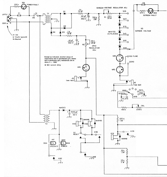
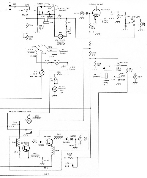
Fig 1 - Tetrode-amplifier control and protection circuit, including connections to a companion amplifier. The ALC circuit shown in the shaded box is one that I described previously in QST. See text.
| D1-D4 | Each consists of three 1N4007s in series. |
| D5-D9 | 1N4733. |
| DS1-DS2 | 120-V neon indicator built into fuse holder. |
| DS3-DS4 | 12-V lamp. |
| F1 | 4-A, slow-blow fuse. |
| F2 | 125-mA, fast-blow fuse. |
| J1 | 6-A CEE-22 connector with built-in line filter (BC). |
| J2, J3 | Phono jack. |
| J5, J6 | Phone jack, shorting. |
| K1 | 1-mA-actuated, 10-kΩ-coil SPST relay. |
| K2 | 4-mA-actuated, 750-Ω-coil SPST relay. |
| K3, K4 | 12-V-dc-actuated DPST relay. |
| M1 | 0-1 mA, contact-making ammeter; see text. |
| S2 | SPDT push-button, momentary-contact switch. |
| S3 | DP3T rotary switch, right-hand-position momentary contact (BC no. RO-4). |
| S4 | Double-pole, 8-position rotary switch. |
| T1 | 120-V primary; 800-V, 150-mA center-tapped secondary.* |
| T2 | 120-V primary; 12-V, 2-A secondary. |
| VR1, VR2, VR3 | Voltage regulator (VR150/0D3 tube, available from Fair Radio (see Table 11).* |
| *Component values may differ for amplifiers using tubes other than the 4CX1000A. | |
| AL | All Electronics, Box 567, Van Nuys, CA 91408, tel 800-256-5432; in California, 800-258-6666 (relays, etc). |
| BC | BCD Electro, Box 830119, Richardson, TX 75083, tel 800-456-2233 (switches, etc). |
| CS | Circuit Specialists, Box 3047, Scottsdale, AZ 85257, tel 800-966-0764 (transistors, etc). |
| DK | Digi Key Corp, Box 677, Thief River Falls, MN 56701, tel 800-344-4539 (insisters, etc). |
| FR | Fair Radio Sales, Box 1105, Lima, OH 45802, tel 419-223-2196 (relays, transformers, voltage-regulator tubes, etc). |
The main reason for using ALC is that a class AB, tetrode amplifier cannot be driven into grid current without producing splatter. Therefore, ALC is one of the best ways to maintain maximum, clean output power. I believe the main reason that people believe that tetrodes, in general, produce poor-quality signals is that most tetrode amplifiers don't provide a positive method of preventing overdrive. In my amplifier-control circuit, back-up gridcurrent-overload protection is provided by a 1-mA meter relay. (A meter relay, also known as a contact-making or -breaking meter, is simply a meter with a set of contacts that open or close at a specific meter-deflection level.) I built this amplifier several years before developing the ALC circuit, and now the meter relay isn't really necessary. If you can't find an inexpensive meter relay, you can use an ordinary meter in its place. Just be sure that your ALC is connected and working if you do this!
Plate-current-overload protection is provided by a relay in the HV supply. When plate current over 1 A is sensed, the circuit sends a trip signal to each control panel to open the control relays. Plate-current overload does not remove the high voltage, but simply removes the screen voltage. I hit on this method only after many years of trying to open the 240-V ac primary circuit under overload conditions. All I have to show for my efforts is an interesting collection of relays with welded contacts! This screen-voltage-removal method protects only the tube, however. The HV supply itself is protected from shorts and arcing by a fast-acting fuse. The fuse itself would not protect the tube from moderate plate-circuit-overload conditions, but it is absolutely necessary for safety.
Loss of grid bias causes both the screen and plate circuits to trip out. However, the primary line of defense against grid-bias failure is simple and automatic: The grid-bias supply powers the main control relay, K!. No grid-bias voltage, no go!
Metering
The control circuit provides dedicated metering of grid, screen and plate current. The screen-current meter is a zero-center type, because positive and negative screencurrent conditions can occur during normal tetrode operation.(3) A fourth meter is switched to measure grid, screen or plate voltage, or forward or reflected power (the forward- and reflected-power signals are provided by a directional coupler in the antenna line).
The expense of precision resistors is avoided by using simple, shunt-multiplier meter-calibration circuits using miniature trimmer potentiometers. For the multimeter, l used a meter with scale markings from 0 to 6, so I adjusted the metering circuits to give full-scale readings as follows: grid, 300 V; screen, 600 V; plate, 6 kV; forward power, 2 kW; and reflected power, 200 W.
To allow compensation for minor differences between tubes, S5 is used to select screen voltages between 300 and 325, in 5-V steps. Although the 4CX1000A's data sheet specifies a typical screen voltage of 325, I get 1.5 kW output - and better linearity - with only 300 V on the screen.
To permit tune-up at decreased plate dissipation, the TUNE position puts 150 V on the screen. Although the SCREEN VOLTAGE switch's TUNE position is handy during tune up and for touch-up antenna tuning, the amplifier is not linear when the grid bias is set for linearity at 300- to 325-V screen operation. Therefore, S5's TUNE position can't be used as a means for quick power reduction during SSB operation.
Circuit operation
When you turn on primary ac with S1, grid-bias voltage pulls in relay K1. When the RESET button (S2) is pushed, relay K3 pulls in; when S2 is released, relay K4 pulls in. If excessive grid current is sensed, the contacts associated with meter relay M1 close, causing K1 to drop out. This opens K3's latching circuit, causing K3 and K4 to drop out. In the event of excessive screen current, relay K2 pulls in and causes K1, K3 and K4 to drop out.
If the tube draws excessive plate current, the plate-overload relay causes the RF-deck control relays to open. When this happens, screen-grid voltage is removed from the tube. To limit grid current in this condition (to prevent tube damage if the exciter is still transmitting), a grid-bias resistor is inserted into the circuit by K4B.
This reset system has another advantage: Because it requires pushing the RESET button on initial startup, this control circuit protects its associated amplifier from momentary power-line interruptions by releasing control relays K3 and K4 at the occurrence of such an interruption. This saves the amplifier from unpleasant jolts when primary power returns.
Does the control circuit ever trip out the amplifier? Only when I switch to the wrong antenna, or forget to retune after changing hands, or such foolishness. Just for laughs, I sometimes turn on the screen voltage before enabling the plate voltage! (This is a well-known, big no-no with tetrodes!) This produces screams from visiting hams, but can't hurt a tube in an amplifier that's controlled by this circuit.
For tetrodes, screen current is the best indicator of resonance and loading conditions.(3) Don't try to tune for a plate-current dip. Resonate tetrodes by tuning for maximum screen current. In a stable, grid-driven tetrode amplifier, resonance and peak output are indicated by a peak in screen current. Adjust the loading until this screen-current peak is the value that yields maximum output. After you find the settings for maximum output, increase the loading so that the output at resonance is 5 to 10% less than the maximum available. (That last step produces a narrower signal!)
As I mentioned earlier, I suspect that some of the bad press that tetrodes have received is simply due to overdrive and improper tuning. Dave Meacham, W6EMD, said it best in a QST articles(3) "Never tune a tetrode amplifier for maximum output."
Adjustments
All the control-circuit adjustments are done on the test bench, without the RF deck connected, and without high voltage applied. Because the 4CX1000A's screen grid usually runs more negative than positive, separate screen-overload-adjustment trimmers, with isolating diodes, are provided across K2A.
Set the control-grid-bias-regulator current to 38 mA (in standby), via R2, with a milliammeter attached at J5. Set the screen-regulator current to 10 mA with the control relays engaged. To do this, attach a milliammeter at J6 and adjust R1. This rather low setting provides protection for the screen. The tubes I've used never run positive screen current under normal conditions, but when the amplifier load is accidentally removed, the screen current tends to soar out of control and drives the tube into a runaway condition, resulting in quick tube destruction. With this circuit, when the screen current rises above 10 mA, the screen voltage drops rapidly.
Summary
How are the results, you ask? This control circuit and its companion 1.8 to 54 MHz amplifier have twice helped me win the SSB ARRL Sweepstakes (New Mexico Section). Using this amplifier, I once won the Rocky Mountain Division in an ARRL SSB DX contest (in the all-band category). Using this amplifier on 6 meter in 1987, I set the current Rocky Mountain Division record in the ARRL June VHF QSO Party (with help from the 2-meter rig). I operate mostly on 6 meter, and conditions for catching a new country or grid square on six might be right for only 30 seconds - maybe a whole minute if you're lucky! For this reason, 100% reliability is required. This control circuit has maintained that performance level for the last 18 years.
Notes
- In this article, I'll refer to the control grid and the screen grid of a tetrode as the grid and the screen, respectively, in keeping with common usage of these terms. In the same vein, I'll use plate in lieu of anode.
- M. Mandelkern, "ALC for class AB1 amplifiers," QST, Jul 1986, pp 38-39, 47.
- D. Meacham, "Understanding tetrode screen current," QST, Jul 1961, pp 26-29.
KN5S, Mark Mandelkern.