Home - Techniek - Electronica - Radiotechniek - Radio amateur bladen - QST - Circularly polarized Quagi antennas for space communications
Activity on OSCAR 13 is booming. This low-cost, one- or two-weekend antenna project can help you gear up for satellite communications.
Worldwide DX is commonplace on OSCAR 13. It's not unusual to hear relaxed roundtable QSOs between Asia, Europe and North America without the congestion of the HF bands - all made with transmitter outputs of less than 50 watts! OSCAR 13 is a handy tool that enables you to keep in touch with the gang back home, even when you're an ocean away. This is exactly what I intend to do on a forthcoming trip to Scotland.
Although the commercial antennas I use for OSCAR 13 are not very large, they are certainly not small enough to carry as luggage on a transatlantic flight. The quagi antenna seemed to be the answer to my problem. The quagi is an easy to build, highly effective antenna design developed by Wayne Overbeck, N6NB, that combines the best features of the cubical quad and the linear-element Yagi-Uda beam antenna.(1)(2) A quagi can be built with simple materials and tools at a fraction of the cost of a commercial antenna.
Quagis can be quite portable. If constructed of suitably lightweight stock, a quagi's elements can be removed from the antenna boom and packed in a suitcase for travel. The boom need not be brought along; another boom - made of wood - can be cut and drilled at your destination. Presto - an instant, high-gain VHF or UHF antenna!
The quagi is a linearly polarized antenna, and OSCAR 13 uses circular polarization. This is not a problem if the signals received from the satellite are always circularly polarized. Although OSCAR 13 transmits and receives using right-hand circular polarization, its signals appear to be circularly polarized only when its high-gain antennas are aimed directly at the sub-satellite point.(3)
This usually occurs at apogee. At other times, OSCAR 13's signals appear to be elliptically polarized and - especially when received on a linearly-polarized antenna - may vary drastically in amplitude as the satellite spins on its axis. This effect, called spin modulation, can seriously reduce signal readability.
After experimenting with linearly polarized quagis for satellite communication, I found that spin modulation makes circular polarization highly desirable. But circular polarization usually involves using bulky, helical beam antennas or crossed Yagis that seem rather difficult to build and adjust. I recalled a QST article by D. S. Robertson, VK5RN, that outlined a method of feeding a quad driven element to obtain circular polarization.(4) Why not apply this method to a quagi?
The birth of the circular-mode Quagi
VK5RN used two coaxial feed lines and a 90° delay line to feed a closed loop. Feeding a quad driven element at adjacent corners presents a unique problem, however: Voltage and current maxima exist simultaneously at all four corners of the loop. Because of this, corner-feeding a circularly polarized loop requires that current be driven into feed points where voltage maxima exist. VK5RN solved this problem by using a sleeve balun at both feed points. The balun transformers present a very high impedance to the in-phase voltages. Therefore, current is not driven down the outer conductors of the coaxial feed lines. Turning a circularly polarized loop into a circular-mode quagi requires the addition of only an impedance-matched power divider and orthogonal, parasitic director elements.
Construction of the circular-mode Quagi
Circular-mode quagis, like conventional quagis, are quite easy to construct. Simple hand tools used with a moderate degree of skill suffice for the 145- and 435-MHz antennas described here. Careful measurement of element and phasing-line lengths are very important though, especially for the 435-MHz antenna. Strive to make all measurements to an accuracy of ± 1/16 inch.
Tables 1 and 2 give the dimensions for the 145.9- and 435-MHz antennas. The dimensions given assume the presence of nonconductive booms (wood is suitable). (If you use a metal boom, you'll have to recalculate all the dimensions!) The 145-MHz quagi uses a 14-ft boom; the 435-MHz version uses a 12-ft boom. In both antennas, the boom consists of clear, 1 x 2 pine or fir molding stock. Select straight-grained wood that's free of knots; this will minimize warping of the boom. I tapered both antennas' booms to 5/8-inch square at their driven-element/reflector ends and weatherproofed the booms with wood preservative.
| Element | Length | Interelement | Spacing |
|---|---|---|---|
| R | 85-7/8 in. loop (2.181 m) | R-DE | 20-3/4 in. (527 mm) |
| DE | 81-in. loop (2.057 m) | DE-D1 | 15-9/16 in. (395 mm) |
| D1 | 35-5/8 In. (905 mm) (2 reqd) | D1-D2 | 32-3/4 in. (832 mm) |
| D2 | 35-7/16 in. (900 mm) (2 reqd) | D2-D3 | 17-5/16 in. (440 mm) |
| D3 | 35-1/4 in. (895 mm) (2 reqd) | D3-D4 | 25-7/8 in. (657 mm) |
| D4 | 35-1/16 in. (891 mm) (2 reqd) | D4-D5 | 25-7/8 in. (657 mm) |
| D5 | 34-7/8 in. (886 mm) (2 reqd) | D6-D6 | 25-7/8 in. (657 mm) |
| D6 | 34-11/16 in. (881 mm) (2 reqd) | ||
| Boom: 1 in. x 2 in. x 14 ft (25 mm x 51 mm x 4.27 m) pine or fir, tapered to 5/8 inch (16 mm) at both ends. | |||
| Driven element: No. 12 TW copper-wire loop in square configuration, corner fed. See text. | |||
| Reflector: No. 12 TW copper-wire loop. See text. | |||
| Directors: 1/8-inch-diam (3.175 mm) rod passing through boom orthogonally in horizontal and vertical planes. | |||
| Element | Lengths | Interelement | Spacing |
|---|---|---|---|
| R | 28-in. (711-mm) loop | R-DE | 7 in. (178 mm) |
| DE | 26-5/8-in. (676-mm) loop | DE-Dl | 5-1/4 in. (133 mm) |
| D1 | 11-3/4 in. (298 mm) (2 reqd) | D1-D2 | 11 in. (279 mm) |
| D2 | 11-11/16 in. (297 mm) (2 reqd) | D2-D3 | 5-7/8 in. (149 mm) |
| D3 | 11-5/8 in. (295 mm) (2 reqd) | D3-D4 | 8-3/4 in. (222 mm) |
| D4 | 11-9/16 in. (294 mm) (2 reqd) | D4-D5 | 8-3/4 in. (222 mm) |
| D5 | 11-1/2 in. (292 mm) (2 reqd) | D5-D6 | 8-3/4 in. (222 mm) |
| D6 | 11-7/16 in. (291 mm) (2 reqd) | D6-D7 | 12 in. (305 mm) |
| D7 | 11-3/8 In. (289 mm) (2 reqd) | 07-D8 | 12 in. (305 mm) |
| D8 | 11.5/16 in. (287 mm) (2 reqd) | D8-D9 | 11-1/4 in. (286 mm) |
| D9 | 11-5/16 in. (287 mm) (2 reqd) | 09-D10 | 11-1/2 in. (291 mm) |
| D10 | 11-1/4 in. (286 mm) (2 reqd) | 010-D11 | 9-3/16 in. (233 mm) |
| D11 | 11-3/16 in. (284 mm) (2 reqd) | D11-012 | 12-3/8 in. (314 mm) |
| D12 | 11-1/8-in. (283 mm) (2 reqd) | D12-D13 | l3-3/4 in. (349 mm) |
| D13 | 11-1/16 in. (281 mm) (2 reqd) | ||
| Boom: 1 in. x 2 In. x 12 ft (25 mm x 51 mm x 3.66 m) pine or fir, tapered to 5/8 inch (12 mm) at both ends. | |||
| Driven element: No. 12 TW copper-wire loop in square configuration, corner-fed. See text. | |||
| Reflector: No. 12 TW copper-wire loop. See text. | |||
| Directors: 1/8-inch-diam (3.175 mm) rod passing through boom orthogonally in horizontal and vertical planes. | |||
The directors consist of 1/8-inch-diameter metal rods or wires. (I used copper welding rod bought at a local welding supply store.) In my antennas, I located the vertical directors 1/8 inch in front of the horizontal ones.
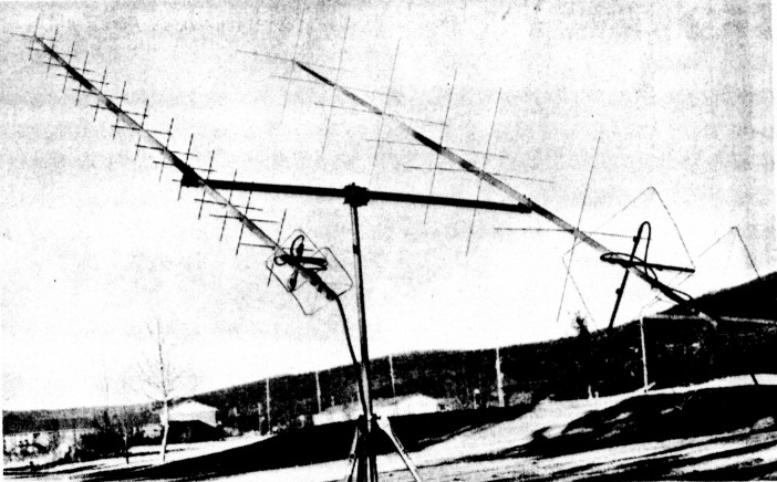
The quad loops are made using no. 12 copper thermal wire (TW). Leave the plastic insulation on the wire or you'll have to recalculate the element lengths. The element dimensions specified in the tables are net dimensions. Therefore, you must allow extra wire length to compensate for overlap where the loop ends are soldered together. Mount the quad loops in a diamond configuration, using strips of acrylic plastic sheet (Plexiglas° is suitable) for support at the loops' corners (voltage maxima). (I used heavy-gage, safety window glazing purchased from a local hardware store.)
Fig 1 shows the sleeve baluns in detail. The baluns consist of brass tubing and sheet stock (available in hobby stores). The tubing is sold in a variety of diameters up to 21/32 inch, in 1/32-inch increments. I used 21/32-inchdiameter stock for the outer tube, and 3/16-inch stock for the inner tube. (RG-58A coaxial cable, with its outer insulation removed, should just fit within the inner tube; this is the case with 3/16-inch-diameter stock.) Larger-diameter brass tubing is usually stocked in 1-ft lengths; I constructed the 2-meter baluns from 5/8-inch-diameter tubing telescoped inside 21/32-inch-diameter tubing - for a total balun length of 19-1/4 inches - and soldered the tubes together. (One-half-inch-diameter copper pipe would probably work well for the outer sleeve-balun tube; the only trade-off would be that copper is heavier than brass. The important thing is to keep the ratio of the outer-tube ID to the inner-tube OD to between 2:1 and 4:1.)
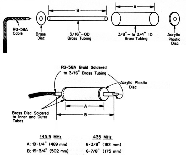
Fig 1 - Detail of the circularly polarized quagis` sleeve baluns. See text.
A disc cut from 0.016 x 3/4-inch brass sheet stock centers the 3/16-inch-diameter tubing in the sleeve and shorts it to the bottom of the sleeve. A similar disc, fashioned from Plexiglas and located at the open end of the balun, supports the 3/16-inch-diameter tubing in the center of the sleeve.
To obtain circular polarization, the power fed to the antenna must be split equally and fed to the horizontal and vertical planes of the antenna. In addition, the RF fed to one plane must be 90° out of phase with the RF fed to the other. To obtain switchable right-and left-hand-circular polarization, a phasing line, 90 electrical degrees long, must be added in series with the feed line to either plane. The feed-point impedance of a quagi is assumed to be 50 0. Each quagi's feed assemblies are fed in parallel via transformers consisting of 90 electrical degrees of 73-11 cable (RG-59A).
Fig 2 shows the details of the phasing and impedance-matching system for a circular-mode quagi. The 145-MHz antenna features switched right- and left-hand polarization using an inexpensive, SPDT, 12-V-dc relay (Radio Shack° no. 275-248). The relay exhibits an insertion loss of 0.5 dB at 145 MHz (acceptable) and 2.2 dB (unacceptable) at 435 MHz. Thus, the 435-MHz antenna is designed for fixed right-hand-circular polarization. A polarization-switching system similar to that used in the 145-MHz quagi can be added to the 435-MHz model if a low-loss coaxial relay is available.
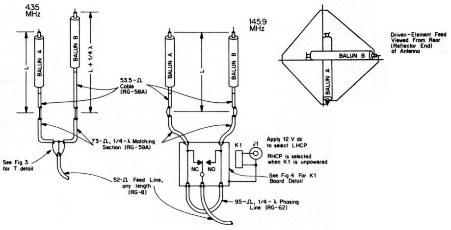
Fig 2 - Feed and phasing systems for the 145.9- and 435-MHz circularly polarized quagis. K1 switches the 145.9-MHz antenna's polarization sense. (The relay used, a Radio Shack 275-248, is too lossy for use at 435 MHz; see text.) See Table 3 for the L and L + ¼λ dimensions, and the lengths of the quagis' matching sections and phasing lines. Fig 3 shows the 435-MHz antenna's T connection in greater detail, and Fig 4 shows how K1 is mounted.
Table 3 lists the coaxial-cable lengths used in the phasing system. To keep costs down, I did not use coaxial fittings on the cable. If you choose to use coaxial fittings - I recommend N or BNC connectors - keep in mind that the cable lengths shown in Table 3 must be shortened to account for the lengths of the fittings.
| 145.9 MHz | 435 MHz | |
|---|---|---|
| 73-Ω matching sections (RG-59A cable; electrical length, ¼λ) | 13-3/8 in. (340 mm) | 4-3/4 in. (121 mm) |
| 93-Ω phasing line (RG-62 cable; electrical length, ¼λ) | 17-1/10 in. (434 mm) | 5-3/4 in. (146 mm) |
| 53.5-Ω L (RG-58A cable) | 23-3/4 in. (603 mm) | 10-7/8 in. (276 mm) |
| 53.5-Ω L + ¼λ (RG-58A cable) | 37 in. (940 mm) | 15-1/4 in. (387 mm) |
| The lengths listed are net; they do not allow for conductor overlap when splicing cables together. The listed cable lengths assume velocity factors of 0.66 for RG-58A and RG-59A, and 0.86 for RG-62. If you substitute cable of another type (with foam instead of solid dielectric, for instance), you'll have to recalculate the phasing-line lengths. | ||
How you splice the phasing cables is important. Push the braid back and away from the end of the cable, cut the dielectric back about 1/8-inch, and carefully solder the inner conductors together. Wind a thin layer of electrical tape over the dielectric to prevent short circuits, dress the cable braids back over the tape, and bind them together securely with fine wire. Don't solder the braid; you may melt the cable dielectric. Tape the junction to protect it from the weather. I made the T-junctions used for the 435-MHz antenna and the 145-MHz circularity switch using a similar technique. Instead of connecting their cable braids by solderless means, however, I quickly soldered the braids to a small piece of copper-clad circuit board (Figs 3 and 4). It's possible to melt the cable dielectric during this operation, but short circuits and dielectric distortion are avoidable with this construction method because they can be seen as they occur.
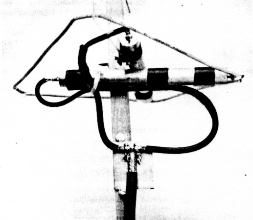
Fig 3 - Cable-braid interconnections at the 435-MHz T are made with solder and a piece of copper-clad PC board. This photo also details the 435-MHz antenna's driven-element feed and acrylic-plastic supports. This photo shows the T before it was weatherproofed with RTV sealant.
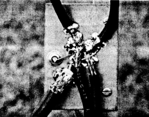
Fig 4 - The 145.9-MHz antenna's polarization-sense-switching relay, K1, is mounted on a piece of unetched PC board. The board also serves as a means of connecting the braids of the feed- and phasing-line, and matching-section, cables together with minimal soldering heat. J1, via which 12 V dc can be applied to K1 to select left-hand circular polarization, is at the left side of the board. This photo was taken before the board was weatherproofed with RTV sealant.
Mounting and positioning the antennas
Before mounting the antennas outside, be certain all of their electrical connections are protected from the weather. A liberal coating of silicone sealant around the T-junction circuit boards, circularity switch and other exposed connections should suffice. A dab of sealant where each director enters the boom prevents director movement.
Because the antennas are intended to generate a circular wavefront, nearby metallic objects, such as a metal antenna mast, may distort the antenna fields and disturb the antennas' gain, patterns and circularity. Because of this, I mounted both antennas on a cross boom made of a 6-ft length of 1-inchdiameter schedule 80 PVC pipe. A wooden broom handle, inserted into the PVC pipe, adds rigidity. A fiberglass cross boom would be a better choice than the wood-supported PVC.
Although satellite antennas do not need to be mounted high above ground, they should be mounted clear of obstructions.(5) At 435 MHz, a large tree with dense foliage acts as an attenuator between the antenna and satellite. On the other hand, mounting the antenna on a tall tower, or far from the trans mitter, to clear nearby obstructions, tends to substitute feed-line loss for obstruction loss.
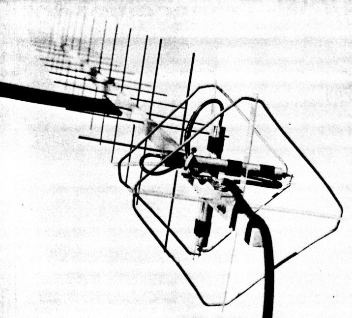
Fig 5 - The 435-MHz, circularly polarized quagi in place and ready for action.
Antenna performance
Not having access to an antenna test range, I based the performance of my circular-mode quagis on comparisons with popular commercial antennas used for satellite communications. A KLM 435-18C 18-element crossed Yagi served as the 435-MHz reference standard, and a KLM 2M-14C 14-element crossed Yagi served as the 2-meter reference standard. In several on-the-air comparisons made through OSCAR 13, the 435-MHz circular-mode quagi exhibited approximately the same gain and circularity characteristics as the commercial antenna. The gain was somewhat less than expected for an antenna with this boom length, but still quite respectable for an antenna costing one-tenth as much as the commercial antenna! Losses in the balun and phasing system probably contributed to the gain being less than expected.
Conversely, the 2-meter quagi outperformed the commercial antenna by about 1 dB. Switching to the opposite polarization sense, when receiving nearly ideal circularly polarized signals from OSCAR 13, resulted in signal attenuation exceeding 20 dB. This compares favorably with the results obtained using the commercial antenna.
Summary
The antennas described in this article offer a cost-effective alternative to commercial satellite-communication antennas. Anyone capable of using simple hand tools with a moderate degree of skill, and who adheres to the dimensions and construction information I've provided, should have no difficulty reproducing these antennas and obtaining the same results.
No antenna article is complete without some mention of spectacular on-the-air results. In this case, my second two-way OSCAR-13 SSB contact using these antennas (and 50 watts) was with Alan, FO5LQ, in Tahiti. Good signals? Of course!
Notes
- W. Overbeck, "The VHF Quagi," QST, Apr 1977, pp 11-14.
- W. Overbeck, "The Long-Boom Quagi," QST, Feb 1978, pp 20-21.
- V. Riportella, "Getting on the New OSCAR," Part 2, Amateur Satellite Communications, QST, Oct 1988, pp 83-84.
- D. Robertson, "The 'Quadraquad' - Circular Polarization the Easy Way,"QST, Apr 1984, pp 16-18.
- V. Riportella, "Getting on the New OSCAR," Part 1, Amateur Satellite Communications, QST, Sep 1988, pp 85-86.
W3PM/GM4YRE, Gene Marcus.