Home - Techniek - Electronica - Radiotechniek - Radio amateur bladen - QST - A triband microwave dish feed
Been looking for a slick way to get on 2304, 3456 and 5760 MHz with a single dish antenna? Look no farther!
Many hams today think of microwaves as the province of wizards and experimenters. Fortunately, that stigma is disappearing now that commercial transverters, amplifiers, antennas and other needed accessories have become widely available, and now that no-tunetransverters(1)(2) and simplified construction ideas are in wide use. This construction article is intended for everyone; no machine tools or exotic materials are needed. In fact, this project doesn't require anything expensive or hard to obtain. After the parts are gathered, you can accomplish the construction work in one concentrated evening, or over a leisurely weekend. It's a great project for groups interested in starting up some microwave work for events such as the ARRL VHF/UHF contests.
A triband microwave antenna? Why not? If we can do it for HF, we can do it for the microwaves! This feed covers the 2304, 3456 and 5760-MHz bands in one unit that's designed for use in a single dish - with no adjustments - while you switch among the three bands. If you want to build your own dish feed, the simplicity of this design makes it a real winner. And, it's available - ready to mount to your feed line or connector - from Down East Micro wave.(3) Dish antennas are available at hamfests and from other sources.(4)
The past
I used to use separate feeds for each band. These were the well-known, dipole/ splash-plate feeds, which are excellent performers. These feeds require machine work to build, and often quite a lot of fussing to change one for another when switching bands. The alternative is to have a separate dish for each band, which is not very practical for a fixed station, and is simply unworkable for portable operation. Another disadvantage is the cost of the dipole/splash-plate feeds: After the large initial investment ($70 or so each if purchased new), the possibility of damage still looms. When the wind picks up, as it is wont to do, the dish may fall over on its face, squashing the feed.
Initial requirements
After building a new triband SSB rig for the microwaves, I decided that a new feed arrangement was also needed to simplify setup and operation. I developed a list of requirements based on my past experience with dishes:
- The new system must cover all three hands at once. (No more feed changing during DX pileups!) Also, no adjustments should be needed when changing bands, such as moving the mounting hardware to accommodate differing phase centers.
- Complete broadbandedness is not desirable; the antenna should reject signals outside of the amateur bands, such as radar, satellite-TV uplinks, etc.
- It should be easy to build (a PC board would be best). No machine work should be required; hand tools only.
- It should be cheap. (Not so much crying when it's broken during a windy mountaintop expedition, as spares can be on hand.)
- No exotic materials should be needed. It must be made from commonly available parts.
- Must be rugged and easy to carry (flat is good).
- Must not be affected too adversely by rain. My dipole/splash-plate feeds have a section of transmission line open to the air. Here in Oregon, the frequent rain fills up those feeds, rendering them useless until emptied (and often leaving them corroded as well).
- Performance must not be more than 2 dB worse than the single-band feeds, and hopefully not even that bad.
The resulting triband feed meets all of these goals. The feed is etched on both sides of a standard FR4 (G-10) circuit board, then sprayed with clear urethane coating to protect the copper against weathering. The board requires no holes, nor any connections between the front and back sides of the circuit board. See Fig 1. The finished assembly is shown in Fig 2, mounted in a dish with semirigid coax.
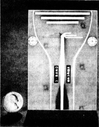
Fig 1 - The triband dish feed is etched on common FR4 PC-board material.
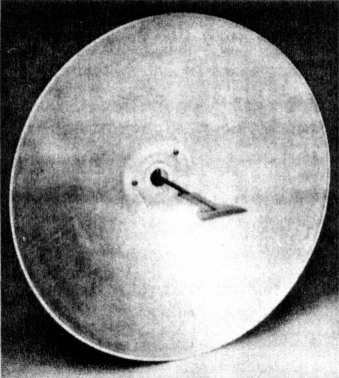
Fig 2 - The first prototype triband feed, mounted in a 19-inch dish, has performed well from my rooftop for almost two years.
How it Works
The triband feed is a variation of the original dish feeds, which consisted of a dipole driven element and a single reflector. The triband feed has three driven elements attached to a common feed point, and three separate reflectors. The lengths of the three driven elements have been adjusted to compensate for proximity to, and the detuning effects of, the other elements.
The elements are positioned for a common phase center for all three bands. This obviates the need for adjustments when changing bands. The 5760-MHz dipole is farthest from the dish surface. The lower-frequency dipoles distort the 5760-MHz dipole's radiation pattern more than if the order was reversed, but this placement facilitates the common phase center.
The balun is a simple, slowly tapered transition from microstripline at the end of the board where the connector mounts, to balanced line as it moves toward the dipoles. Although it's a compromise to allow printing the whole assembly, this technique is surprisingly effective.
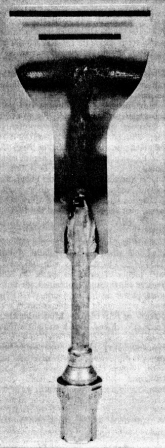
Fig 4 - This triband feed was tested with 200 W of 2304-MHz RF; it failed. Don't apply more than 20 W to this feed!
Material and results
The SWR is typically better than 1.5:1 on the two lower bands and better than 2:1 on 5760 MHz. See Fig 3. SWR varies somewhat from one feed to another, and is affected slightly by the mounting method. The feed helps to reject some of the extraneous signals sometimes found outside the amateur bands on the same mountaintops that you'll occupy for your DXpeditions!
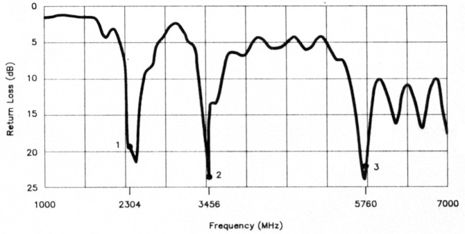
Fig 3 - A network-analyzer plot showing the return loss (another way of expressing SWR) of a prototype feed. The greater the return loss, the better the SWR. (For more information on return loss, see K. Kleinschmidt, Ed., The 1990 ARRL Handbook (Newington: ARRL, 1989), p 35-38, and W. Hayward and D. DeMaw, Solid-State Design for the Radio Amateur, second printing (Newington: ARRL, 1986), pp 154-155.
The board material dramatically affects these results. I used a 3- × 4-½-inch piece of 1/16-inch-thick FR4 material with I-ounce copper on both sides, and presensitized with positive-acting resist. (Although I used Injectorall type 4013 board from the local parts store, PC-board material without the positive resist shouldn't affect performance.) Other manufacturers' FR4 boards will probably work fine, but if you use another material (phenolic, Teflon®, epoxy-paper, etc), or one of a different thickness, you will have to make major changes to the dimensions of both the transmission line and the elements.
I have tested only the configuration shown here. It works so well, both electrically and mechanically, that I didn't try others. Teflon (either woven mat or the amorphous types, such as Rogers Duroid™) would exhibit slightly lower loss, but at the price of much less mechanical strength.
I used a protective spray coating from the local parts store (Fine-L-Kote UR spray urethane conformal coating, made by Tech Spray, stock no. 1711-16S). I suspect that many other plastic spray coatings will work fine, but 1 have not tried any, so, as in all microwave work, if you change the recipe, you are on your own. Extensive tests have shown that the resonant frequencies of the feed move less than 25 MHz after the spray is applied, causing only negligible changes in SWR. The copper patterns have been designed to account for the presence of the plastic coating, but you can omit it without performance problems. Still, I recommend the plastic coating - especially around the edges of the board, which can absorb water if left unprotected for outdoor use.
When tested in a 1-meter dish (f/D = 0.31), and compared to dipole/splash-plate feeds, the triband feed's gain, although somewhat less than that of optimized single-band units, is still very good. See Table 1. Some of this loss is due to suboptimal dish illumination and some is a result of dielectric loss in the circuit-board material (more on this later). The three reflectors are not optimal (they replace three separate round discs), and the three driven elements "argue" with each other. But that's the price of a PC-board, do-all feed! For critical long-haul, weak-signal work, consider keeping a set of optimized, single-band feeds handy.
This feed handles enough power for a very effective mountaintop station, and I have regularly put 20 W through it with no trouble. But there is a limit: Al Ward, WB5LUA, tested a copy of this feed with 200 W of 2304-MHz RF for an extended time during the January 1990 ARRL VHF Sweepstakes contest. Even a small amount of dielectric loss was enough to precipitate spectacular heat damage, as shown in Fig 4. The board was burned so badly that all the copper fell off, predictably causing a rather severe SWR increase. I recommend not applying more than 20 W to this feed!(5)
| Frequency Triband | Feed Loss |
|---|---|
| 2304 MHz | 0.75 dB |
| 3456 MHz | 1.25 dB |
| 5760 MHz | 1.5 dB |
Construction
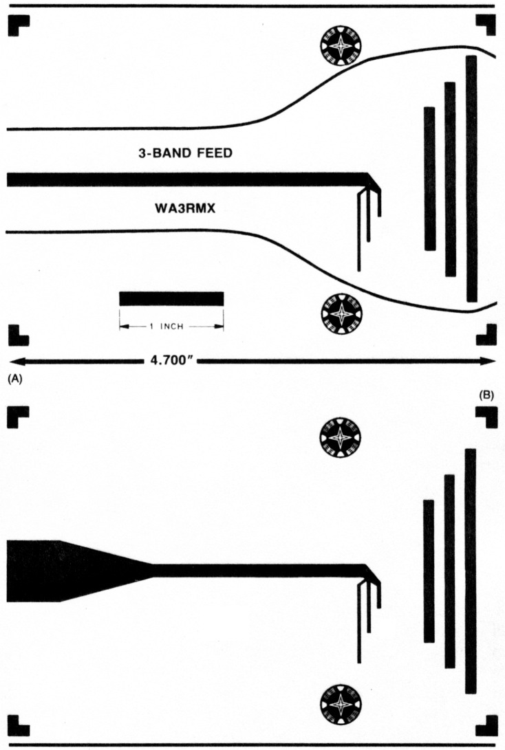
Fig 5 - PC-board pattern for the triband dish feed. At A, the front pattern is shown. It includes a rule for checking the board size before etching. At B, the back side of the board is shown. Accurate registration of the patterns is important; the alignment should be within 0.030 inch for best performance.
To build the triband feed, first etch the patterns on the front and back of the board. The full-size patterns are shown in Fig 5. The front pattern is dimensioned so that you can easily check the board size before etching. Fig 6 is an X-ray view of the board showing the feed's apparent phase center. Accurate registration of the front and back patterns is fairly critical; testing has shown that the two sides should be aligned to within at least 0.030 inch for good performance and low SWR. Pattern alignment can be achieved either by drilling two pilot holes in the unetched board at the locations of the two bullseyes on the artwork, or by carefully taping the edges of the artwork together and clamping the unetched board between them before exposure. (I prefer the drilling method.) After etching and washing the board, cut away the excess board material just inside the cut lines on the front artwork. Be sure to remove all metal from the cut lines.
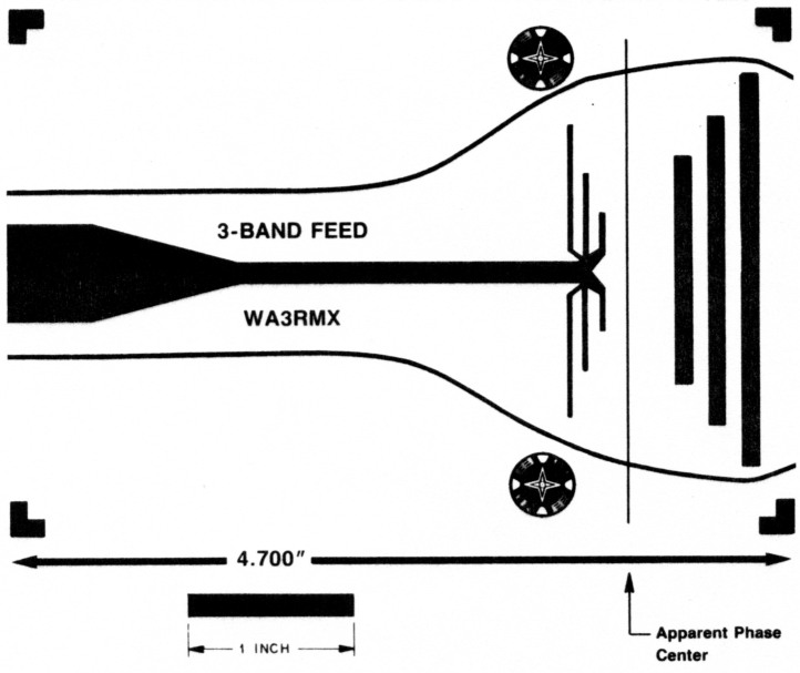
Fig 6 - An X-ray view of the PC board, showing the apparent phase center of the feed. Place this part of the feed at the focal point of your dish, as described in the text.
Mount a connector to the board in whatever arrangement suits your dish. I suggest you use semirigid 50-Ω coax, either 0.250 or 0.375 inch in diameter, with a connector to fit the feed line to the rig (see the title photo). Prepare the board and the coax to fit each other as shown in Fig 7. You can also mount a connector right to the board, as shown in Fig 8, trimming off the excess copper on the top. In any case, use the shortest leads possible: Even 1/16 inch or less excess wire kills performance at 5760 MHz!
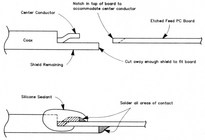
Fig 7 - Prepare the Hardline for mounting to the dish-feed PC board by cutting away half the shield and dielectric from the cable over a distance long enough to ensure a solid mechanical connection to the board. Then, bend the center conductor slightly and fit it into a notch in the PC board, as described in the text.
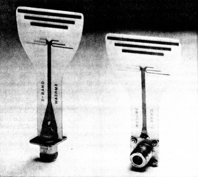
Fig 8 - Two prototype triband feeds with N connectors mounted directly to the PC boards. When mounting connectors this way, be sure to minimize stress on the feed resulting from feed-line strain.
I built one triband feed using the popular 0.141-inch-diameter semirigid coax (UT-141), as this is readily available at hamfests and from suppliers that cater to microwave hobbyists. Although this works electrically, UT-141 is too weak to hold the feed in place except with very gentle handling. If UT-141 is all that you have available, use it; it works fine for light-duty service. If you do use such small Hardline, flatten the part of the shield to be soldered to the back side of the board. The board is thicker than the spacing from the center conductor to the shield, and the center conductor shouldn't be as long as would be necessary for it to wrap around to the front side of the board.
I use a GR874 connector on my portable version of the feed, which allows quick assembly and disassembly, but it also allows water to enter the connection if it's used in heavy rain. My permanently mounted versions all use N connectors for water-resistant, low-SWR connections. If you expect to use the feed in the rain, it is a good idea to mount it in the dish at a slight angle from the horizontal to allow runoff. (If water pools on the flat upper surface of the feed, dielectric loading will detune the antenna.)
After the mechanical and electrical assembly is finished, spray the plastic coating onto the board. After it dries, apply some electronics-grade (non-acidic) silicone sealant to the area of the solder connection to seal out moisture, especially if the feed is to be used extensively outdoors. For this purpose, I use Dow no. 3145 silicone sealant.
Now, mount the feed in the dish, with the apparent phase center (Fig 6) at the focal point of the dish. My tests showed that, although it's a compromise, this is the best feed placement for all three bands. To find the focal point of a dish, use the equation f = D2 ÷ 16h, where D is dish diameter and h is dish depth (see Fig 9). The triband feed works well with dishes having f/D ratios from 0.25 to 0.4, which is the range over which I've tested the feed.
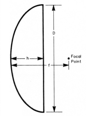
Fig 9 - Measure the proportions of your dish and calculate the location of the focus as described in the text.
Operation
With one of these feeds in a 30-inchdiameter dish, I have made 80-mile 2304-MHz FM contacts with 100 mWwith plenty of signal to spare. On SSB, greater range can be obtained, or much lower power used. Lynn Hurd, WB7UNU, and I have made 115-mile contacts with 50 mW of SSB on 2304 MHz using these feeds at each end - stuck straight up into the air, without dishes! In a test to see what is possible using minimal power over a lineof-sight path, we set up 50-mW SSB rigs with 29-inch dishes at each end, each equipped with a triband feed. Communicating over a 66-mile path, we added attenuators in the feed line to one rig until the SSB signal was just barely readable. With 50 dB of added attenuation, we still had readable signals. (This corresponds to 1/2 micro watt of transmitter power to the antenna!) We were pleased.
Roger McCoy, W7ADV, and I made a 130-mile 2304-MHz contact over an obstructed path using 29-inch dishes equipped with triband feeds at each end, by using the tip of Mt Hood (12,000 feet above sea level) as a knife-edge diffractor. We first tried this with 20 W and had fine signals, so we also tried CW and managed a weak contact with only 100 mW.
At the extreme, I have even used a tri-band feed to make 10-mile contacts with 25 mW on 10 GHz. Although far from optimal, the feed still radiates a signal at 3 cm! Three VUCC awards each on 2304, 3456 and 5760 MHz have been earned with copies of this feed. WB7UNU (grid CN85NL) and I (CN85NM) each use these feeds in I9-inch dishes on our roofs, and regularly chat on 2304 and 3456 MHz (5760-MHz signals don't make it too well through the grove of trees on my neighbor's property).
I hope this article helps generate more activity on the microwave bands. With the triband feed and the simple transverters now on the market, it's easier than ever before to put together lots of roving stations for the VHF and microwave contests. VUCC, here we come!
Acknowledgments
Thanks to Deane Kidd, W7TYR, for his help with the artwork and his untiring encouragement. Also, thanks to WB5LUA for his high-power tests, and to W7ADV and WB7UNU for their help field-testing the prototypes.
Notes
- R. Campbell, "A No-Tune Transverter for 3456 MHz," QST, Jun 1989, pp 21-26.
- No-tune transverter kits for 903, 1296, 2304 and 3456 MHz, as well as preamps and accessories, are available from Down East Microwave, RR 1, Box 2310, Troy, ME 04987, tel 207-948-3741.
- See Note 2. The triband feed is priced at $20 plus shipping and handling. The ARRL and OST in no way warrant this offer.
- Spun-aluminum dishes are available in several sizes (24, 36, 48, 60 and 72 inches) from Antenna Center, 505 Oak St, Calumet, MI 49913, tel 906-337-5062. The 24- and 36-inch models are UPS-shippable; prices range from $36 (24 in.) to $190 (72 in.) plus shipping and handling.
- For those who have higher power available and want the advantages of the triband feed, I plan to submit a follow-up article to QEX that will give a board pattern for Duroid material. That feed won't be nearly as rugged as the FR4 board, but it will handle more power.
WA3RMX, Tom Hill.