Home - Techniek - Electronica - Radiotechniek - Radio amateur bladen - QST - A high-dynamic-range MF/HF receiver front end
Read a two-tone IMD dynamic range specification of over 100 dB for an MF/HF receiver and you'll probably also see the qualifications "preamp off," "500 Hz IF bandwidth" and "signal spacing, 100 kHz." This front end hits 111 dB with preamp on, a 2.4 kHz IF bandwidth and the ARRL standard test-signal spacing of 20 kHz.
Proliferation of high-powered transmitters and electronic noise pollution imposes severe signal-handling requirements on modern receivers. Strong signal-handling capability has received significant attention from the manufacturers and reviewers of MF/HF amateur equipment during the last decade. Despite these technical advances, there is definitely room for some improvement. Yaesu's FT-1000, a state-of-the-art transceiver, sports a claimed dynamic range of 108 dB and an intercept point of +32 dBm (RF amplifier off, 500 Hz IF bandwidth, 50 kHz spacing). For a 2.4 kHz bandwidth, this dynamic range would drop to 103.5 dB.
This article shows how to build a front end which achieves a two-tone dynamic range of 111 dB and an intercept point of + 33 dBm with 20 kHz test-tone spacing, RF amplifier on, and using an IF bandwidth of 2.4 kHz. That this performance can be realized with a preamplifier in line is significant. It allows the realization of a receiver that combines strong signal-handling capability with excellent sensitivity, a challenge to any receiver designer. The circuit can be adjusted using test equipment available to most construction-minded amateurs, and its 50-ohm modular construction provides flexibility and encourages experimentation.
| Gain (Av) (dB) | -0.3 | 8 | -7 | 8 | -6 | -2 | - |
|---|---|---|---|---|---|---|---|
| Noise Figure (NF) (dB) | 0.3 | 2 | 7 | 2.5 | 6 | 2 | 3 |
| Third-Order Input Intercept (IP,3in) (dBm) | +33 | +32.7 | +40.7 | +34.5 | -- | -- | - |
| 1 dB Input Compression Point (PC) (dBm) | +15.3 | +15 | +23 | +18 | -- | -- | - |
| 1 dB Input Desense Point (P0) (dBm) | +14.3 | +14 | +22 | -- | -- | -- | - |
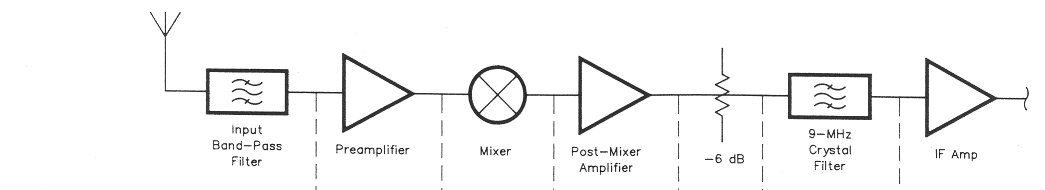
Fig 1 - Stage-by-stage gain, noise figure, third-order input intercept, 1 dB compression point and 1 dB desensitization point performance of the high-dynamic-range front end.
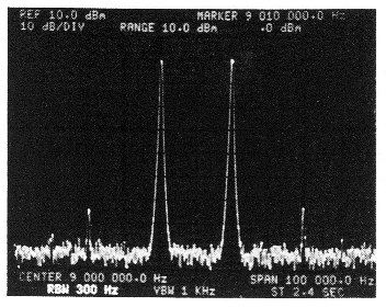
A spectrum analysis of the front end's performance, preamplifier off, while converting two 0 dBm (1 milliwatt) 14 MHz signals spaced 20 kHz apart to the front end's 9 MHz IF. These appear at 8990 and 9010 kHz, with the system's third-order intermodulation products (8970 and 9030 kHz) down 64 dB relative to either test signal. This equates to a third-order input intercept of +42 dBm. (spectrum photograph by the author)
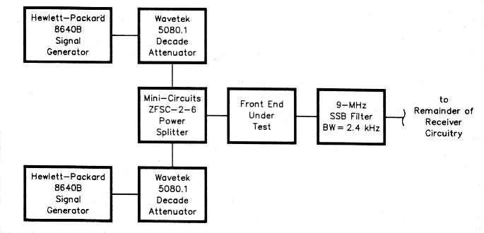
Fig 2 - This test setup was used to make the measurements tabulated in Fig 1.
Front-End Design Considerations
The primary motivation was to design a front end capable of withstanding an abundance of strong signals several kilohertz away from a desired weak station. A traditional approach to this problem is the use of switchable preamplifiers and attenuators. Professional communications equipment sometimes employs PIN-diode attenuators,(1) correlating attenuation to signal level. Depending on the implementation, these methods may have one drawback: Sensitivity suffers, so the suppression of strong interfering signals is achieved at the cost of losing weak stations. Therefore, early in the design of this front end, it was decided that a preamplifier should precede the mixer to establish a low system noise figure.
Fig 1 shows a partial block diagram of a single-conversion receiver. This article covers only the preamplifier, mixer and the post-mixer amplifier in detail. A low-loss, band-pass input filter serves to protect the front end from strong out-of-band signals. The filter insertion loss is assumed to be 0.3 dB. For the sake of calculations, the IF amplifier noise figure is assumed to be 3 dB. Every block preceding the 9-MHz filter has 50-ohm input and output impedances. This greatly facilitates block replacement, promotes experimentation, and makes possible the removal of the preamplifier to connect the input band-pass filter directly to the mixer.
Measurement and Calibration Results
The measurement results are summarized in Fig 1. The preamplifier was evaluated at 14 MHz, and the mixer and post-mixer amplifier at 9 MHz. The test setup is shown in Fig 2. Table 1 summarizes the system measurement and calculation results.(2) Table 1 indicates that the preamplifier allows the achievement of a receiver sensitivity of 0.15 µV, on par with or better than any commercially produced MF/HF amateurtransceiver, while keeping third-order input intercept and dynamic range at the respectable levels of + 33 dBm and 111 dB, respectively. Extensive experiments on 14 MHz prove the front end's performance to be quite adequate under the most adverse receiving conditions.
Those wishing more flexibility can implement a preamp on/off option, although the intent of the design was to avoid the need of this switch. Amateurs who find a sensitivity of 0.32 µV adequate for their needs may choose not to use the preamplifier at all. If this is done, the front end becomes truly "uncrunchable" with an impressive third-order input intercept point of +41 dBm and a spurious-free dynamic range of 112 dB. The 1 dB input desensitization point (3), (4), (5) reaches + 22 dBm in this case, a signal level of 2.8 V RMS at the antenna connector!
Overall System Considerations
Although sensitivity and dynamic range are primarily determined by the quality of the front end, some of the remaining receiver stages are of considerable importance. The IF amplifier should have an input signal handling capability of several volts, its distortion characteristics should be adequate, and its noise figure must be low enough not to appreciably degrade the front end's noise figure. A good crystal filter is a must; its shape factor should be 1.8 or better, and its ultimate attenuation should exceed 100 dB. Cascading two filters, one before the IF amplifier, and one after, should be considered as a way of improving the selectivity and also reducing the wideband noise generated by the IF amplifier. The product detector should not degrade the signal coming from the IF strip, and the audio amplifier's frequency response should be tailored with low- and high-pass filtering. Finally, extra care should be taken when designing the local oscillator (LO). A poorly designed oscillator may negate improvements in the front-end's dynamic range. Excessively high close-in phase noise (6), (7) may degrade the receiver's ability to separate closely spaced signals. If we assume that the crystal filter provides out-of-band rejection of 100 dB at an offset of 2.0 kHz, the LO's phase noise must be better than -133 dBc/Hz at a 2.0 kHz offset to preserve the filter's performance. High far-out phase noise may raise the receiver noise floor; this can degrade the receiver's dynamic range. The dynamic range limited by phase noise should be equal to or better than the dynamic range limited by IMD.(8) Calculations show that the LO's farout phase noise should be better than -145 dBc/Hz. Although the LO spectral purity requirements are quite stringent, they can be met by employing an LC-type oscillator with a high-Q coil.
| Preamplifier | With | Without |
|---|---|---|
| Third-Order Input Intercept (IP3in, dBm) | +33 | +41 |
| 1 dB Input Compression Point (Pc, dBm) | +15.3 | +23.3 |
| 1 dB Input Desensitization Point (Po, dBm) | + 14.3 | + 22.3 |
| System Noise Figure (NF, dB) | 6.6 | 12.9 |
| Minimum Discernible Signal (MDS, dBm) | -133.4 | -127.1 |
| Sensitivity for 10 dB (S+N)/N Ratio in 50 Ω (Vs, µV RMS) | 0.15 | 0.32 |
| Spurious-Free Dynamic Range (SFDR, dB)* | 111.0 | 112.1 |
| Blocking Dynamic Range (BDR, dB) | 147.7 | 149.4 |
| *Also known as two-tone dynamic range; measured at ARRL Lab standard testsignal spacing of 20 kHz. | ||
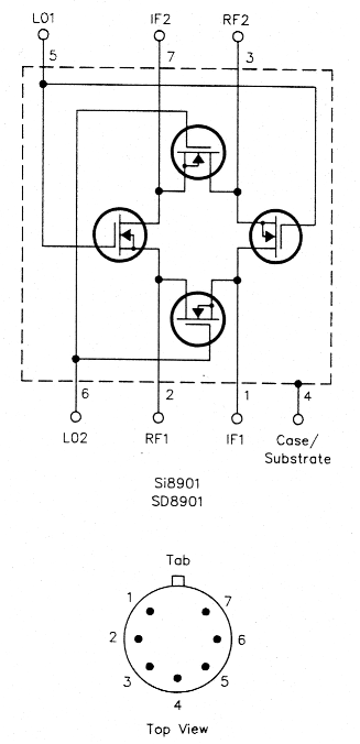
Fig 3 - The front end uses a Siliconix Si8901 DMOS FET quad mixer. Siliconix has since discontinued this part, but an exact replacement (the SD8901) is available from Calogic Corporation.
Circuit Description
Mixer
This stage received special attention since its characteristics have a profound effect on dynamic range. Numerous articles have been written covering the performance of different types of mixers. For those interested in this subject, the works cited at Notes 1, 5, 9, 10, 11 and Additional References 1 through 4 are recommended.
After an extensive survey and experimentation, it was concluded that a passive mixer with active devices can provide the highest input intercept point. The Siliconix Si8901, a monolithic quad DMOS FET designed by Ed Oxner, KB6QJ, was chosen for the mixer. This excellent device was specifically designed for mixer applications and truly belongs at every experimenter's bench. Siliconix Application Note AN85-29 provides detailed information needed for the design. Fig 3 shows the Si8901's circuitry and pinout. Fig 4 shows the mixer/diplexer schematic. T1 matches the 50-ohm source (the preamplifier) to U2's RF port, and T2 matches U2's IF port to a 50 Ω load, the post-mixer amplifier.
In a commutation mixer, there is a compromise between conversion loss and inter-modulation distortion. The impedance ratios of transmission-line transformers T1 and T2 are chosen to achieve low inter-modulation distortion while keeping conversion loss at an acceptable level.
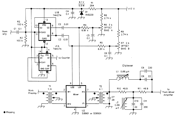
Fig 4 - The front end's mixer circuitry applies the Si8901/SD8901 in conjunction with a 74HC74 dual flip-flop, a diplexer network and a VFO operating in the 10.5 MHz region, twice the frequency necessary to convert 14-MHz signals to the system's 9 MHz IF. Both 74HC74 sections divide the LO frequency by two and square it; one section (U1A) provides LO output for a frequency counter, and the other (U1B) drives the mixer's LO port. The OFFSET BIAS controls adjust mixer balance. D1 sets the 74HC74's supply voltage at a level considerably higher than the part's specified 6-V maximum; see text. See the parts list sidebar for component information.
The LO waveform applied to U2 is of great importance. To achieve a high intercept point, the LO drive must approach an ideal square wave with a 50% duty cycle.(10), (11) Flip-flop U1B divides the LO signal frequency by two and provides 50% duty cycle square waves at its complimentary outputs. The offset bias adjustment potentiometers, R6 and R7, allow compensation for mismatch among the Si8901's MOSFETs and ensure that the commutation mixer switches operate in a 50% duty cycle mode. UTA provides a signal that can be applied to a digital frequency counter.
The mixer's intercept point also depends on the LO drive level. Zener diode D1 establishes the power supply voltage for U 1 and, therefore, the voltage swing at the mixer LO port. In the interest of obtaining a high intercept point, a 9.1 V diode is used at D1. This voltage exceeds the 74HC74's maximum supply specification. Experiments with samples from different manufacturers show that there is a considerable safety margin, however: The 74HC74s tested failed when the power supply was adjusted to around 11 V. Those who feel uncomfortable in exceeding the part's maximum rating may use a 6.8-V Zener diode at the cost of a few decibels in the intercept point value. Since double-balanced mixers are sensitive to IF port mismatches,(12) and a reactive load can cause an increase in conversion loss and degradation of the third-order intercept point, a band-pass diplexer follows the mixer. The diplexer comprises L1, C8, C9, L2, C1O, C11, R10 and R11. The 9 MHz signal passes through this network with minimum attenuation, while out-ofpassband signals over a wide frequency range are dissipated. Resistor R1O presents a 50-ohm impedance to the mixer, while R 1 presents a 50-ohm impedance to the input of the post-mixer amplifier. C7 cancels the inductive reactance of the load presented to the mixer's IF port.
The measured performance of this circuitis: third-order output intercept, + 35 dBm; 1 dB output compression point, + 16 dBm; 1 dB output desensitization (blocking) point, + 15 dBm; insertion loss, 7 dB.
Preamplifier
To preserve the mixer's dynamic range, the preamplifier's output intercept point should exceed the mixer input intercept point by at least 3 dB, and its compression point should exceed the mixer's by at least 1 dB.(13) The preamplifier's design criteria are as follows: third-order output intercept, >45 dBm; 1 dB output compression point, >24 dBm; gain between 6 and 9 dB; noise figure <3.0 dB; -1 dB frequency response, 1.8-30 MHz.
If conventional resistive feedback techniques were used to meet the design objectives, the required transistor standing current would become prohibitively high, resulting in a high noise figure. Therefore, a combination of a "noiseless feedback" method(14-18) and a push-pull configuration was tried, and resulted in the circuit shown in Fig 5.
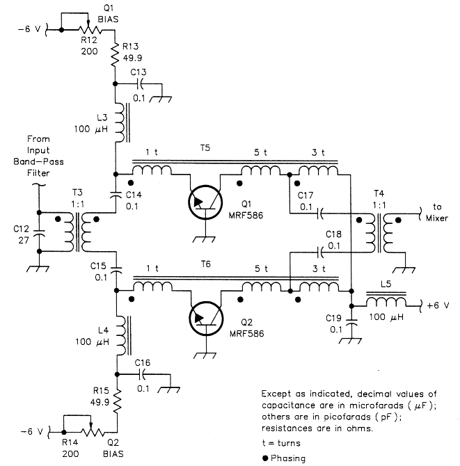
Fig 5 - The front end's input preamplifier consists of two MRF586 transistors operating in push-pull. The push-pull configuration allows the realization of a high output intercept point at moderate device standing currents. The BIAS controls individually adjust the transistors' collector currents to the desired 25 mA. See the parts list sidebar for component information.
The MRF586 is a high-frequency transistor designed for use in low-noise, ultralinear amplifiers and packaged in a TO-205 case. Used in a common-base configuration, this device provides a low noise figure because its optimum source resistance is close to 50 ohms. Bias controls R12 and R14 allow the collector current of each transistor to be adjusted to the desired value of 25 mA. T3 matches the amplifier input to the 50 ohm bandpass input filter; T4 matches the preamp output to the mixer signal port.
Transformers T5 and T6 are designed to couple part of the collector signal back into the emitter (negative feedback), set the gain to 8 dB, and set the input and output impedances to 50 ohms. C12 cancels the inductive reactance of the source presented to the mixer's RF port at 14 MHz. (In a multiband receiver, this capacitor may be part of switchable preselector filters.) The measured performance of the circuit is: third-order output intercept, + 48 dBm; 1 dB output compression point, +25 dBm; gain, 8.0 dB; noise figure, 2.0 dB; -1 dB frequency response 1-40 MHz. This performance fully meets the preamplifier design goals.
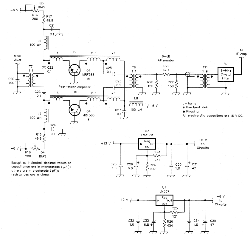
Fig 6 - Another push-pull MRF586 pair, this time biased to 40 mA of collector current per device, serves as the front end's post-mixer amplifier. A 1:9 transformer steps the amplifier's 50-ohm output up to 450 ohms for a reasonable match to the system's 500-ohm crystal filter. The 6 dB pad is essential in preserving this stage's high dynamic range: It buffers the amplifier from load mismatch by "flattening" the crystal filter's impedance versus frequency characteristic as illustrated in Figs 7 and 8. The values of capacitors C28-C35 are in F.
Post-Mixer Amplifier
Although the post-mixer amplifier (Fig 6) uses the same basic configuration as the preamplifier, its design criteria are different. The post-mixer amplifier's input intercept point should exceed the mixer output intercept point by at least 3 dB, and its compression point should exceed the mixer's by at least 1 dB. The post-mixer amplifier must therefore exhibit these characteristics: third-order input intercept, >38 dBm; 1 dB input compression point, >17 dBm; gain between 6 and 9 dB; and noise figure, <3.0 dB.
These design goals could easily be met if the post-mixer amplifier had a purely resistive termination. However, the amplifier must drive a crystal filter, the impedance of which varies considerably with frequency. Connecting the post-mixer amplifier to the crystal filter via a matching transformer would severely degrade the amplifier's third-order intercept point. Inserting resistive attenuation between the amplifier and filter reduces this effect to an acceptable level, as shown by Figs 7 and 8.
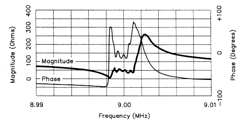
Fig 7 - The crystal filter's input impedance as seen by the postmixer amplifier through a 1:9 matching transformer. The reflections caused by this characteristic seriously degrade the amplifier's strong-signal performance if the 6 dB pad shown in Fig 6 is omitted.
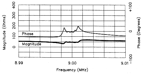
Fig 8 - The filter impedance as seen by the amplifier through the 1:9 transformer and a 6 dB pad. The reflections still occur, they must for the filter to act as a filter, but the pad reduces their magnitude sufficiently to preserve the amplifier's high dynamic range.
BIAS controls R16 and R18 allow adjustment of the MRF586s' collector current to 40 mA per device. This value is 15 mA higher than the preamplifier's device standing currents to overcome the negative effects of the reactive load on the postmixer amplifier's intercept point. T11, a transmission-line transformer, matches the crystal filter's impedance (500 ohms in this case) to the amplifier's 50 Ω output impedance. C20 cancels the inductive reactance of the source presented to the amplifier's input. The measured performance of the post-mixer amplifier, terminated by a 9 MHz filter via the 6 dB pad, is: third-order input intercept, + 34 dBm; 1 dB input compression point, + 18 dBm; gain, 8.0 dB; and noise figure, 2.5 dB. In spite of the measures taken, the input intercept point requirement has not been met. Overall system measurements indicate, however, that the mixer's third-order input intercept point has been degraded by less than 1.5 dB (40.7 dB versus 42 dB) and is still very high.
Construction
The three modules are enclosed in separate, unpainted aluminum boxes. Each module's components are mounted on Vector 8007 board (perforated, with a solid copper plane on one side). The circuit components are mounted on the solid copper side, which serves as a ground plane. Vector T68 pins serve as terminal posts as necessary. All modules' signal inputs and outputs are made via BNC connectors; RG-174 coaxial cable interconnects the modules.
Properly built and shielded, the amplifiers should not oscillate. Because they operate in push-pull, strict symmetry should be observed in constructing the upper and lower halves of each amplifier.
The matching transformers specified at T1 and T2 (1:4 ratio) T3, T4, T7 and T8 (1:1 ratio) and T11 (9:1) are commercial units. If home-built matching transformers are used instead, they should be transmission-line types and highly symmetrical. Transformers T5, T6, T9 and T10 are homemade as shown in Fig 9.
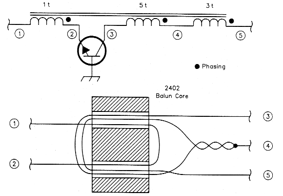
Fig 9 - Transformers T5, T6, T9 and T10 are wound with #32 wire on two-hole ferrite cores (see the parts list sidebar for core information). Wind the 1-turn winding (1-2) first, the 3-turn winding (3-4) second and the 5-turn winding (4-5) third.
Alignment
Amplifiers
Adjust controls R12 and R14, Q1 BIAS and Q2 BIAS (Fig 5), for a collector current of 25 mA per device. Adjust controls R16 and R18, Q3 BIAS and Q4 BIAS, for a collector current of 40 mA per device.
Mixer
The diplexer inductors, L1 and L2, must be aligned first. If the mixer is a part of an assembled receiver, inject a signal (100 mV P-P at, say, 14.250 MHz) into the antenna terminal. Tune the receiver to thisfrequency and adjust L1 and L2 for maximum signal while observing the signal at the post-mixer amplifier's output on an oscilloscope.
As an alternative method, apply a 14.250 MHz, 100 mV P-P signal to the preamplifier input. Using another signal generator, apply 4 V P-P at 10.5 MHz to the input (from VFO) of U1 (Fig 4). Peak L1 and L2 as described above.
For optimum performance, adjust R6 and R7 (OFFSET BIAS A and OFFSET BIAS B) while viewing the mixer's output spectrum with a spectrum analyzer. A two-tone IMD test setup (Fig 2) is required. (Detailed information on performing this test can be obtained from the works cited in Notes 3, 4, 5 and 10, and Additional References 1 and 8.) Connect the spectrum analyzer to the post-mixer amplifier output. Adjust R6 and R7 to minimize third-order-IMD products. Monitor the mixer insertion loss while doing this; it should be around 7 dB.
If a spectrum analyzer is unavailable, another method can be used. A 9-MHz IF strip with defeatable AGC is required. Turn off its AGC, connect it to the post-mixer amplifier, and connect a scope to its output. Tune the front end's VFO to convert one of its third-order IMD products (2f1 - f2 or 2f2 - f1, where f1 and f2 are the test-signal frequencies) to 9.000 MHz. Adjust R6 and R7 to minimize the level of this signal.
Summary
By properly applying known design principles, radio amateurs can construct a high-performance front end which combines a very high intercept point with excellent sensitivity. Used with a low-noise LO, the front end described in this article achieves a wide dynamic range even with its preamplifier stage in line. A receiver incorporating such a front end can provide strong-signal performance that rivals orexceeds that of most commercial equipment available to the amateur.
Notes
- U. Rohde, "Recent developments in circuits and techniques for HF communications receivers," ham radio, Apr 1980, pp 20-25.
- An information package detailing the calculations on which this data is based, as well as a list of suppliers for the components listed in the "Parts List for the High-Dynamic Range Front End" sidebar, is available free of charge from the Technical Department Secretary, ARRL, 225 Main St, Newington CT 06111. Please mark your request MAKHINSON FRONT-END TEMPLATE and include a business-size SASE.
- C. Drentea, Radio Communication Receivers (Blue Ridge Summit, PA: TAB Books Inc, 1982), pp 88-135.
- R. Watson, "Guidelines for receiver analysis," Microwaves and RF, Dec 1986, pp 113-122.
- Wideband signal processing component catalog, VARI-L Company, Denver, CO.
- J. Grebenkemper, "Phase Noise and Its Effects on Amateur Communications," Part 1, QST, Mar 1988, pp 14-20; Part Two, Apr 1988, pp 22-25. Also see Feedback, QST, May 1988, p 44.
- P. Chadwick, "Phase Noise Intermodulation and Dynamic Range," Frequency Dividers and Synthesisers IC Handbook, Plessey Semiconductors, 1988.
- See Note 7.
- E. Oxner, "Designing a Super-High Dynamic Range Double-Balanced Mixer," Application Note AN 85-2 (Santa Clara, CA: Siliconix, 1986).
- V. Drozdov, Lyubitel'skie kv Transiveri (Amateur HF Transceivers), in Russian, Moscow, USSR, 1988.
- See Note 9.
- P. Drexler, "Effect of Termination Mismatches on Double-Balanced Mixers," Microwave Journal, Jan 1986, pp 187-190.
- E. Red, "Daten, Fakten, HF-Grundschaltungen, 50 ohm-Technik," in German or Russian, Franzis-Verlag GmbH, Munich, 1986.
- See Note 1.
- U. Rohde, "High dynamic range receiver input stages," ham radio, Oct 1975, pp 26-31.
- D. Norton, "High Dynamic Range Transistor Amplifier Using Lossless Feedback," Microwave Journal, May 1976, p 53.
- J. Reisert, "High dynamic range receivers," ham radio, Nov 1984, pp 97-105.
- See Note 13.
Additional References
- D. DeMaw, Practical RF Design Manual (Englewood Cliffs, NJ: Prentice-Hall Inc, 1982), pp 23-25.
- E. Oxner, "Junction FETs in Active Double-Balanced Mixers," Application Note AN 73-4 (Santa Clara: Siliconix, 1973).
- U. Rohde, "Performance capability of active mixers," Part 1, ham radio, Mar 1982, pp 30-35; Part 2, ham radio, Apr 1982, pp 38-44.
- W. Hayward, "Experiments with Primitive FET Mixers," RF Design, Nov 1990, pp 39-48.
- N. Ayrandjian, "Simple Computation of Spurious-Free Dynamic Range," RF Design, Jan 1987, pp 65-66.
- W. Richardson, "IMD and intercept points of cascaded stages," ham radio, Nov 1984, pp 28-34.
- W. Hayward and D. DeMaw, Solid-State Design for the Radio Amateur (Newington: ARRL, 1986), Chapter 6: Advanced Receiver Concepts.
- RF/IF Signal Processing Handbook, Vol 1 (Brooklyn, NY: Mini-Circuits, 1985), pp 7-23.
Parts List for the High-Dynamic Range Front End
Unless indicated otherwise, all of the circuits' resistors are 1/4 W 1% tolerance, and all of its capacitors are 20% tolerance ceramic. C7 - C12 and C20 are dipped mica, polyester film or epoxy-coated ceramic.
| C7 | 39 pF 10%. |
| C8, C10 | 330 pF 5%. |
| C9, C11 | 22 pF 5%. |
| C12 | 27 pF 10%. |
| C20 | 100 pF 10%. |
| D1 | 9.1 V, 0.5 W Zener diode, 1 N5239 suitable. See text. |
| L1, L2 | Toko 332PN-T1012Z (DigiKey TK5130) 1.0 µH variable inductor. |
| L3-L8 | 100 µH RF choke. |
| Q1-Q4 | Motorola MRF586 RF transistor. Use heat sink (Thermalloy 2228B or Aavid 3257) on Q3 and 04. |
| R6, R7 | 2 kΩ multiturn potentiometer. |
| R12, R14, R16, R18 | 200 Ω multiturn potentiometer. |
| T1, T2 | Mini-Circuits T4-1 4:1 RF transformer. |
| T3, T4, T7, T8 | Mini-Circuits T1-1T 1:1 RF transformer. |
| T5, T6, T9, T10 | Homemade trifilar transformer wound with #32 enameled wire on Amidon BN-43-2402 core (Fair-Rite 2843002402) as per Fig 9. |
| T11 | Mini-Circuits T9-1 9:1 RF transformer. |
| U1 | 74HC74 CMOS flip-flop. |
| U2 | Calogic Corporation SD8901HD mixer (replaces the Siliconix Si8901 HD). Siliconix has discontinued the Si8901; the Calogic SD8901 is an exact replacement. |
| U3 | LM317MP adjustable voltage regulator IC. |
| U4 | LM337MP adjustable voltage regulator IC. |
A list of the names and addresses of parts suppliers, keyed to the components in this list, is available as detailed in Note 2.
N6NWP, Jacob Makhinson