Home - Techniek - Electronica - Radiotechniek - Radio amateur bladen - QST - The NRY, A simple, effective wire antenna for 80 through 10 meters
Known as a broadside collinear curtain array, this antenna is simple to build, rakes in DX signals and has gain over a dipole on all the bands it covers!
N6NR, Rick Olsen.
Hams' thoughts ultimately turn to antennas. So it was with me a while ago. I had just moved to the emerald beauty of the Pacific Northwest and began pondering the 160-foot-tall Douglas firs in my backyard. I had considered putting up a crank-up tower, but decided that neighbors, architectural committees and crank-ups don't mix. Then I thought about topping a tree. Nope - I moved here because I love these trees.I started sniffing around for alternatives. I obtained a copy of fellow ARRL Technical Advisor Roy (W7EL) Lewallen's antenna-modeling program, ELNEC, along with a copy of The ARRL Antenna Book, and began to incubate the seeds of what would become my most enjoyable antenna project since I built a four-element quad back in 1974.
Hanging ropes from big trees is not a new idea.(1)(2) I began by pacing off the distances between the monsters in my yard so I would know how much space I had to work with and how I could optimally direct my signal to places like Europe, Africa and the Caribbean.
Next came the selection of a configuration. Because the trees are approximately 120 feet apart, my first choice was a multielement collinear array. But a good friend, Terry Conboy, N6RY (in NRY, I'm the NR and he's the RY), suggested stacking a pair of extended double Zepps. I filed his suggestion away in my memory for the time being. I started my analysis.
The ARRL Antenna Book, on page 8-32, describes the basic function of the collinear array. In sum, it concentrates energy perpendicular to the wire, hence the term broadside array. This antenna's physical layout and pattern are shown in Fig 1. Such an antenna' s gain can be increased by varying the end-toend spacing of the elements.(3)
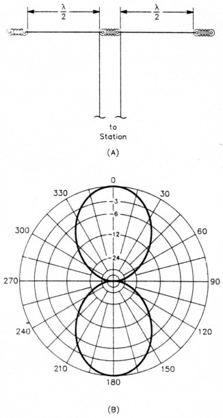
Fig 1 - A two-element collinear array (A), also known as two half-waves in phase, is merely two half-wave wire elements placed end to end. This antenna has about 1.5 dB gain over a dipole in the same surroundings, and B shows its free-space pattern.
Chapter 8 goes on to explain three- and four-element arrays. Disappointment set in when I sized a four-element in-line array for 20 meters: It wouldn't fit between the trees! What would fit, however, was a "two-over-two." In fact, depending on the vertical separation, this array might even have some gain over the four-element collinear arrangement.(4)
My choice was made. I wanted to maximize performance on 20 meters and take what I could get on the other bands. I chose two 1-λ, center-fed wires vertically spaced 5/8 λ apart. According to ELNEC, with the array 100 feet high at the top and modeled over lossy ground, this antenna's gain is approximately 12 dBi.(5) Not bad! The only problem is that this antenna's 20-meter feed-point impedance is very high.
Reenter N6RY and the extended double Zepp. Take a look at Fig 2A. The extended double Zepp is simply a 1.25-λ, center-fed wire (two end-to-end 5/8-λ elements). There' s a hidden message here! Have you found it?
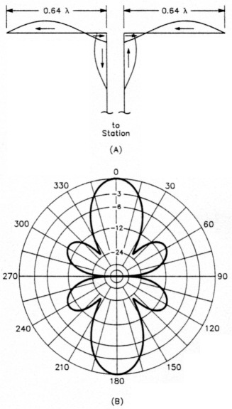
Fig 2 - At A, the physical layout of and current distribution on an extended double Zepp (EDZ), a special case of the two-element collinear array shown in Fig 1 A. This antenna exhibits more gain than the Fig 1 A antenna because lengthening the elements to 5/8 X has the same effect as spacing the element ends of two collinear half-wave elements 0.28 λ apart. (See Note 3.) At B. the antenna's azimuth-plane pattern in free space. This antenna has about 3 dB gain over a dipole in the same surroundings.
Well, at first, I didn't either. Terry explained to me that the extended double Zepp (EDZ) is essentially two half-wave collinear elements spaced just over 1/4-λ apart. The extended double Zepp's added gain over two half waves in phase comes not from the extra 0.28-λ of wire between them, but from the increased end-to-end spacing of the outermost pair of half wave elements. (Radiation from the inner 0.28-λ actually works against that from the outer half-waves, but the gain increase from the new element spacing more than overcomes this disadvantage.) Figs lB and 2B are similar. The EDZ has broader lobes and useful smaller lobes, both of which are attractive for a fixed array.
Sure enough, it was right in front of me all the time in the Antenna Book (page 8-34, fifth paragraph). In fact, the whole darned array was right in front of me in Chapter 8! I just needed some help piecing it all together. I modeled this array every way I could imagine, looking for the best possible performance. My wife didn't see me in the evenings for two weeks! Fig 3 shows the final configuration.
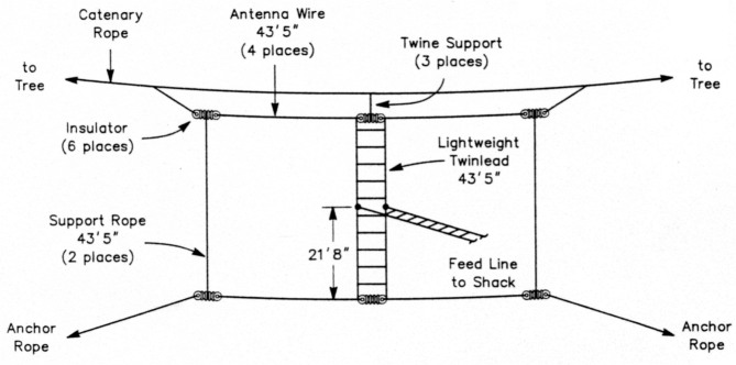
Fig 3 - The broadside collinear curtain array - the NRY - in its final configuration. This antenna is cut for 20 meters, but works well on all the HFham bands. The array hangs from a catenary rope via three short lengths of twine. The lower end insulators are supported by ropes to those of the top wire, and the center insulators are joined by the phasing line, which is 43 feet, 5 inches of parallel-wire feed line. The feeder to the radio is made of the same type of line connected at the halfway point on the phasing line.
Figs 4, 5 and 6 show some of the results of my modeling. I used a design frequency of 14.2 MHz, a height of 100 feet above ground (for the top wire), elements made of #14 copper wire, and ground coefficients typical of the Pacific Northwest. All the elements in this array are fed in phase, as described in a bit.
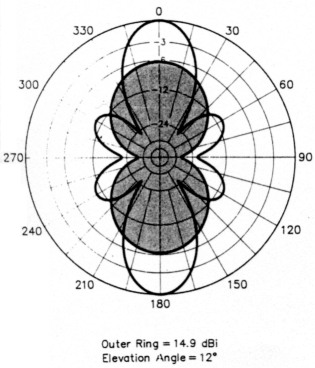
Fig 4 - The NRY's 14-MHz azimuth-plane pattern with the bottom wire at 56.5 feet and top wire at 100 feet. For comparison, the shaded part shows the pattern of a half-wavelength, 14-MHz dipole at 78 feet (the same height as the NRY's feed point).
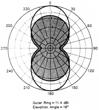
Fig 5 - The NRY's 10.1-MHz azimuth-plane pattern with the bottom wire at 56.5 feet and top wire at 100 feet. For comparison, the shaded part shows the pattern of a half-wavelength, 10.1-MHz dipole at 78 feet (the same height as the NRY's feed point).
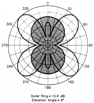
Fig 6 - The NRY's 18.1-MHz azimuth-plane pattern with the bottom wire at 56.5 feet and top wire at 100 feet. For comparison, the shaded part shows the pattern of a half-wavelength, 18.1-MHz dipole at 78 feet (the same height as the NRY's feed point).
As the figures show, the antenna's gain and patterns are impressive. On the 80- and 40-meter bands, the antenna has remarkably dipole-like patterns and gains and seems to work at least as well as a dipole in the same height range. On the higher bands, it works much better than a dipole. Its predicted gains in my installation are 9, 11 and 14 dBi at 7, 10.1 and 14 MHz, respectively. At 18.1 MHz (Fig 6) and above, the array begins to take on long-wire properties. It has several major lobes in directions closer to the wire axis, which the lower-frequency patterns don't provide.
To help you evaluate the NRY's patterns, Figs 4-6 superimpose the patterns of halfwave dipoles cut for 10.1, 14 and 18.1 MHz, respectively, on the NRY's patterns. These comparisons assume that the dipole is the same height as the NRY's feed point (halfway between the elements, or about 22 feet lower than the top wire), and over the same ground.
You may wonder about this antenna's effectiveness as a function of height. According to the Antenna Book, arrays like this have the best gain when the lower element is at least 1/2 λ above the ground (33 feet at 14 MHz). And, of course, as with all horizontally polarized antennas, this array's radiation angle decreases as you raise the antenna, which makes for better DX performance. The bottom line is that for DX work, you don't have to get the array up 100 feet for it to work well - you just need to put it up as high as you can. For closer-in coverage, it will work well at lower heights.
Another advantage of this array is that its feed-point impedances are manageable. To maintain my goal of broadband use, I decided to feed the antenna as shown in Fig 3. This is the "lazy-H" configuration described starting on page 8-37 of The ARRLAntenna Book. The attractiveness of this configuration is that it doesn't rely on specific phasing-line lengths to work properly. To the extent made possible by the different mutual impedances between each element and the ground, the phase relationship between elements remains constant regardless of frequency.
Final dimensions
The antenna's physical dimensions (86 feet, 10 inches long and 43 feet, 5 inches high, not counting insulators) are easy to remember because the height is half the length. Because the antenna is basically 1.25 (5/4) λ long, center-fed and vertically spaced 5/8 λ apart, you can easily scale it to whatever band you like. For instance, to scale it to 10 meters, divide all the dimensions by two (28 MHz/14 MHz = 2).
Construction
Now for the really fun stuff: putting this thing up in the air! Building the antenna is a breeze. It took me all of about an hour to cut and solder the wires and attach the tethers. The harder part was preparing the trees.
If you have a friend like Bernie Olshausen, N6RUX, you have it made. He's a crack shot with a slingshot, similar to that described by Wade Calvert, WA9EZY, in QST a couple of years back.(6)
Once Bernie landed the fishing lines over the right tree limbs, the next job was to pull up some lightweight twine (we used seiner twine - the stuff fish nets are made of) with the fishing line. This is important; rope sometimes snags as it goes over limbs, and you don't want to try to pull it over with 6-pound-test fishing line! With the twine, we pulled up some 800-pound-test nylon rope with a pulley on one end, using another piece of nylon rope through :he pulley to act as a catenary for the array.
It's important to use a strong, weather-resistant catenary rope to hang the array, because the antenna loses its desirable properties quickly when it takes on the shape of a V. You can expect a 2-dB gain decrease at 20 meters with a 20° variance from the flat-top configuration. The rope, therefore, must be strong enough to minimize droop and maintain integrity in the sun and wind. We'll get back to the rope in a minute.
For the phasing harness I used low-loss, 300-Ω twinlead. Any parallel-wire feeder should work fine. Don't use coaxial cable in the feed system. It's too heavy, unbalances the array and has very high loss when operated at a high mismatch.(7)
To assemble the feed system, I used porcelain insulators and equal lengths of 300-Ω line. I then cut the #14 antenna wire to the proper length and soldered it to the feed system in a standard dipole configuration.
Next came the tethers. For an antenna almost 87 feet wide and 43 feet tall, you need to provide some means of maintaining the proper element spacings. I used equal lengths of seiner twine (nylon or dacron rope would also work fine) to vertically space the element ends. I also attached plenty of line to the lower end insulators so I could tie them to the appropriate fence posts once the antenna was in the air. See Fig 3.
The catenary rope is the trickiest part. The antenna won't hang right if you don't attach the top three insulators in the right spot. I know - I did it wrong the first time!
I cut a piece of catenary rope 95 to 100 feet long and carefully marked the center. Next, I measured the distances from the center to each end of the array. (The array itself is a handy measuring line.) Then I added about 10 more inches and marked the line. I'll tell you why in a minute.
Then I cut three pieces of twine, each about 24 inches long. At the center of the catenary rope, I carefully opened the rope weave and passed about 6 inches of twine through it, then let the catenary rope retake its natural shape. Wrapping the twine around the rope several times on either side of the joint relieved the tension placed on the rope introduced by passing the twine through it.(8) I then tied the other end of the twine to the top center insulator so that the spacing between the rope and the insulator is 12 inches.
After doing that, I attached the twine at the 'end marks on the catenary rope in the same manner. The distance to the end insulators is 18 to 20 inches. This causes the ends to hang off the rope at an angle and provides strain relief.
If you use a braided rope (with a weave you can't open to pass twine through it), one good alternative is to use insulators in the catenary rope (at the points where I attached the twine) as tie points for the array.
Now you're ready to haul the antenna up on the lanyards. Consult your US Navy Marlinspike Seamanship manual (just kidding, of course) and join the ends of the catenary to the lanyards that are hopefully by now through the pulleys, up in the trees. Use a strong knot that won't slip.
Before hoisting the array into the sky, make sure that the connections to the feed harness at the top and bottom are the same (ie, that the left elements both attach to the same wire in the twinlead). This thing does not work right if the top and bottom are fed 180° out of phase!
Now you're ready to haul it up and connect the feed line to the antenna tuner. Check to make sure that the symmetry and top-to-bottom wire spacings are within reasonable limits, then tie the bottom tethers off so that the bottom wire is as flat as you can make it.
You're done!
This is quite an effective antenna. I've installed two of them: One is boresighted on the Middle East and works like gangbusters into Europe as well; the other favors the Caribbean and most of the US. In the first three months after putting them up, I worked 105 countries on CW, including some rare ones, with a 100-watt transceiver. I'm surprised at how easily I can bust pileups - especially on 30 and 20 meters.
I hope you have an opportunity to try this array on for size. Don't limit yourself to just the backyard, either: It's a great Field Day antenna, to say the least. It also comes in handy for emergency work where you need a gain antenna.
You don't have to be a rocket scientist to design effective antennas! Your old friend The ARRL Antenna Book, and other ARRL publications, like Walt (W2DU) Maxwell's Reflections, the Handbook, the Antenna Compendium series and Wilfred Caron's Antenna Impedance Matching, are serious reference guides and sources of numerous ideas. It doesn't hurt to have your favorite antenna-modeling software loaded on your PC, either!
Notes
- 0. Brede, "The Care and Feeding of an Amateur's Favorite Antenna Support - the Tree," QST, Sep 1989, pp 26-28, 40.
- J. Hall, ed, The ARRL Antenna Book, Chapter 22 and pp 4-3 and 15-3.
- The ARRL Antenna Book, Fig 8-38, p 8-32, illustrates how gain varies with the spacing of the two adjacent element ends.
- The Antenna Book's Fig 8-45, p 8-35, suggests that a spacing of 5/8 to 2/3 λ yields good broadside gain. For the four-element array, upwards of 8.5 dBi gain is obtainable.
- dBi means decibels relative to an isotropic radiator (point source) in free space. It does not denote gain relative to a point source above real ground, or a dipole in any surroundings.
- W. Calvert, "The EZY-Launcher," QST, Jun 1991, pp 34-35.
- The ARRL Antenna Book shows how coaxial-cable loss varies with matched loss and SWR in Fig 18, p 24-18. (The Antenna Book also contains a table of matched loss per 100 feet as functions of frequency and cable type in Fig 26, p 24-18).
- If you use braided rope for the catenary, you'll need to use another method to secure the seiner twine to the catenary rope.