Home - Techniek - Electronica - Radiotechniek - Radio amateur bladen - QST - A high-directivity receiving antenna for 3.8 MHz
How about a front-to-back ratio of 25 to 45 dB? Three tuned, phased, ground-mounted loops can provide it in less than 100 feet of linear space.
The old saying that you can't work them if you can't hear them certainly applies to 75 meters. Seventy-five-meter DXing from western New York is challenging for this reason. It has been estimated that European DX stations are typically 20 dB weaker in this area than they are near the Atlantic Ocean; farther inland, they are even weaker. Since signal and static levels are generally high at 3.8 MHz, one solution to copying weak European signals is to improve their signal-to-noise ratio with receiving-antenna directivity.
A 400-foot Beverage receiving antenna, directed to Europe, allowed me to work many stations that were not copiable on a ¼-wavelength vertical. Improving my transmitting antenna to a pair of phased verticals reduced the Beverage's advantage to slight. I decided to use Brian Beezley's MN antenna analysis program(1) to determine if a better ground-mounted receive antenna could be built.
Nearly all directive antennas have unwanted responses - often less than 20 dB down - on the sides or back of their patterns. Noise and interference contributed by these responses limit the receiving signal-to-noise that can be obtained. In this way, a Beverage antenna's side lobes workagainst the achievement of high directivity (see Fig 1).
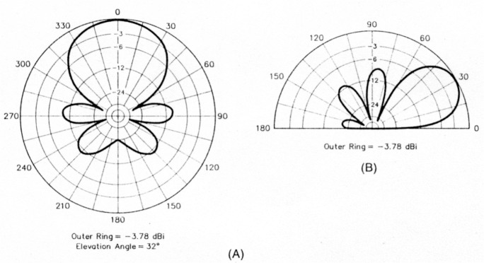
Fig 1 - A 400-foot, 8-foot-high terminated Beverage antenna displays significant side lobes that compromise its ability to reject noise and interference in the horizontal plane (A). Evaluating the Fig 1 antenna in the vertical plane (B) tells a similar story. The secondary vertical lobes bring in interference and noise from near-vertical-incidence signals - that is, from sources that are relatively local. (patterns modeled over average earth at 3.8 MHz with MN)
After I reviewed several antenna textbooks,(2)(3)(4) the most likely candidate seemed to be the end-fire binomial array - an arrangement in which three or more elements are fed with an ever-increasing phase delay (from hack to front), with the element currents diminishing from the center element outward. A three-element antenna of this type has appeared in several amateur publications,(5) and usually has 1/4-wave spacing with a progressive 90° delay per element and a 1:2:1 current distribution. Computer analysis shows that this antenna can give excellent directivity with an optimized spacing somewhat less than ¼ wavelength and progressive phase delays of 135°.
But what type of element should be used? Mathematicians analyze binomial arrays using what are called isotropic elements - idealized radiation sources so small that their dimensions are insignificant relative to wavelength. At 3.8 MHz, a wavelength is about 259 feet, so, seeking practical performance at par with that predicted by theory, and not wanting to put down a large ground system, 1 chose to use tuned loops instead of vertical elements. The receiving loop has many advantages over monopoles, as discussed by Hart.(6) In addition to being a low-noise antenna, the loop is easily tuned and matched to 50 Ω and requires no ground system. I chose to use square loop elements, each 5 feet per side and mounted 2 feet above ground. Small loops have a null broadside to their plane, so these loops are oriented edge to edge, toward the target.
Pattern predictions
I wanted the array's pattern to be easily reversible, so I picked element phase delays of 90° or 135° to simplify the feed system. A 1:2:1 element current ratio gave optimum directivity with 40-foot (center-to-center) element spacing. Fig 2 shows the predicted azimuth and elevation patterns obtainable with an antenna configured in this way. Over average earth, the optimum arrival angle is 29°, but the antenna has an excellent pattern at low and high angles (typical of loops, per Hart). Its horizontal 3-dB beamwidth is 78°.
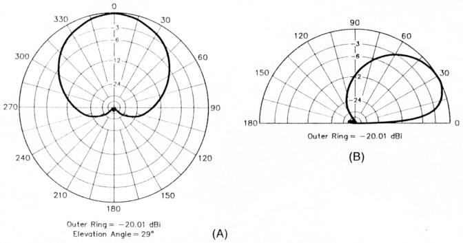
Fig 2 - Properly spaced, phased and driven, three ground-mounted loops configured as a binomial end-lire array can provide an almost perfect cardioid (heart-shaped) horizontal response (A), with a beamwidth almost identical to that of the Beverage modeled in Fig 1. The loop array's lower gain (at least 16 dB lower than that of the Beverage) requires preamplification, but does not compromise weak-signal performance at 3.8 MHz. In the vertical plane (B), the loop array provides much better rearward-signal discrimination than the Beverage.
Electrical loop design
Fig 3 shows the schematic of the loops. Small, tuned loops generally have low efficiency, but this is not an important factor for receiving at 3.8 MHz. Using the radiation resistance formula in Hart's book, the loops' radiation resistance computes to about 0.005 Ω each. Measurements have shown that the total feed resistance, which includes the wire loss, transformer and capacitor losses, is about 1Ω. Based on these numbers, the efficiency works out to 0.5%, or -23 dB. Although a low-noise, high-dynamic-range preamplifier is required to preserve system sensitivity, the normal QRN level at 75 meters, not the array's inefficiency, limits system performance.
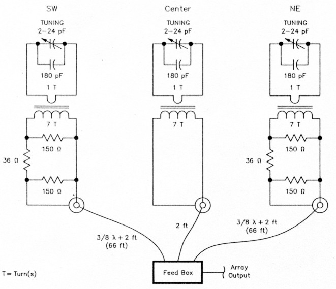
Fig 3 - Each loop resonates at 3.8 MHz with a tuning capacitance of about 190 pF; the loops are spaced 40 feet apart (center-to-center). A transformer (turns ratio 7:1) matches each loop to 5042 line; 6-dB pads (use noninductive resistors) reduce the current contributed by the outer loops to half that contributed by the center one. The feed-line lengths shown are for RG-58A cable. Fig 5 details the feed-box circuitry.
The array's bandwidth (its region of highest performance) computes to about 20 kHz, although it can be used over most of the 80-meter band. Tuning each loop is accomplished with a low-value trimmer capacitor across a fixed 180-pF capacitor, for a total capacitance of about 190 pF per loop. I recommend using high-quality fixed capacitors, such as those made by ATC, JFD or Vitramon. Ordinary "receiving" variables and dipped micas can be used if low-level RF is applied to the array during adjustment. I applied 5 W to my array during adjustment - a level at which more than 700 Vappears across the loop tuning capacitors. (A sudden SWR or return-loss change during loop adjustment indicates probable capacitor failure.)
Each loop's ferrite matching transformer has a one-turn primary consisting of a brass tube passed through stacked toroidal ferrite cores. Seven turns of insulated wire wound through the tubing form the secondary. The primary connects to the loop; the secondary, to 50Ω coax via coaxial fittings. My transformers are based on commercial assemblies,(7) but you can build your own using hobby brass stock as shown for transistor-final transformers on page 60 of Solid Sane Design for the Radio Amateur.(8) I suggest using four 0.5-inchOD -43 (µ = 850) toroidal ferrite cores per transformer. PC-board material can serve as tube end plates as shown in Solid State Design.
A five-element, end-fire binomial array design
The three-element end-fire binomial array described in this article easily fits into the space previously occupied by my 400-foot Beverage antenna. A five-element array would also fit into that space, so I designed one with the dimensions shown in Table A. Modeling predicts that all of its side and back lobes should down at least 50 dB at all angles of elevation (see Figs A and B). Pattern attenuations of this magnitude may not be achievable in practice because highly precise phasing and element drive are required, but its comforting to know that there is no theoretical reason why directivity exceeding 50 dB cannot be achieved. - WA2WVL
| Element Position | Relative Current | Relative Phase |
|---|---|---|
| Rear | 1 | 270° (or -90°) |
| 4 | 135° (or -225°) | |
| Center | 6 | 0° |
| 4 | -135° | |
| Front | 1 | -270° |
The elements are spaced 50 feet apart (center-to-center) for optimum side-lobe performance.
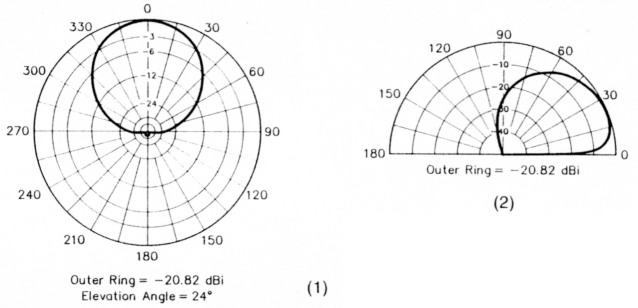
Fig A - Predicted horizontal (1) and vertical (2) performance of a five-element end-fire binomial array. Unlike the other polar plots in this article, which use OSTs standard log-periodic scale, the vertical-plane plot uses a linear-decibel scale to highlight the antenna's clean pattern at high attenuations.
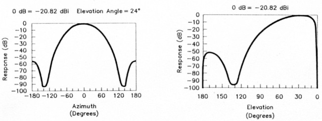
Fig B - Plotting the five-element array's horizontal performance with rectangular coordinates (1) shows its higher pattern attenuations better than the polar plots in Fig A. Critical adjustment of element current and phasing is necessary to approach such attenuations in a practical system. A rectangular-coordinate plot of the five-element array's vertical performance appears at 2.
Construction
Each loop consists of #14 copper wire housed in a PVC-pipe frame. About 13 feet of wire is needed per loop half - in all, roughly 80 feet for a three-element array. The loops are tuned at their tops and fed at their bottoms.
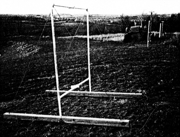
Fig 4 and the title photo show the loop partially assembled and completed. One-inch PVC pipe forms each loop frame. PVC pipe comes in 10-foot lengths, so my loop dimension of 5 feet per side allows the use of standard-length sections without waste. Each loop's tuning capacitors mount in a I-inch cross centered in the loop top. Each loop's feed (a 7:1 transformer and BNC coaxial connector) mounts in an assembly centered in the loop bottom. This assembly consists of 1½- to 1-inch reducers, a 1½-inch cross, a 2- to 1½-inch reducer, a 1½-inch cap and a 2-inch cap. The 2-inch cap holds the loop feed components; the 1½-inch cap closes the uncommitted cross port. The 1½-inch-to 1-inch reducers can be seen on the ends of the two pipes in Fig 4. The necessary PVC cement, crosses, elbows, pipe, reducers and Ts are available where plumbing supplies are sold.
Elbows form the loops' upper corners; Ts, the lower. Sixteen-inch pieces of 1-inch pipe (not visible in Fig 4) cemented into the bottom of the Ts allow the loops to be ground-mounted on timbers.
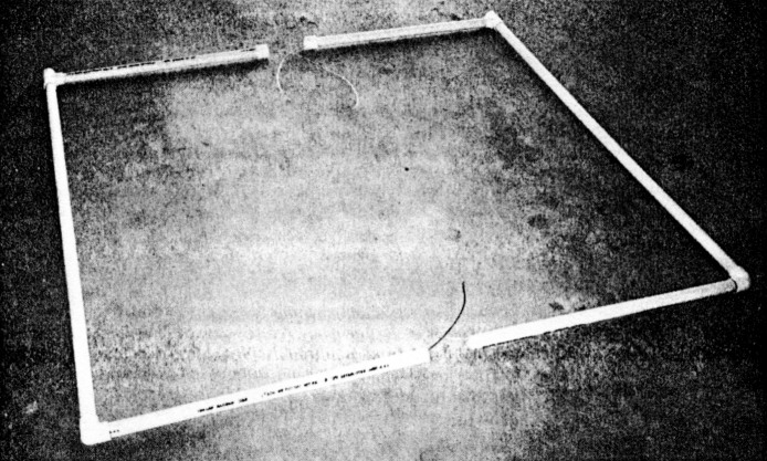
Fig 4 - This loop is ready to receive its center crosses-1-inch for the loop top (foreground) and 11/2-inch for the loop bottom (background, via 1- to 1½-inch adapters).
Build your loops on a flat surface, such as a garage floor, to ensure that the loop sides are in line. Run the wire through each loop's PVC pieces beJine assembling them so you won't have to push the wire through. the loop wires out through the back of the crosses. Tap the sides of the Ts with a block of wood to seat the PVC pipes in the crosses.
Build each loop in halves, cementing all of its fittings except the center crosses. Once the halves' cement has dried, set the halves upright. Without using PVC cement, slip the center crosses on to complete the loop, bringing the loop wires out through the back of the crosses. Tap the sides of the Ts with a block of wood te seat the PVC pipes in the crosses.
I drilled small holes in the crosses to secure the loop-wire ends and create tie points. "Flying lead" construction of the transformer/connector and tuning capacitor assemblies allows them to be easily installed or removed. (Be careful not to reverse any of the transformer connections, as this would add an extra 180° of phase lag in that element and spoil your antenna's performance.)
Ground mounting
Initially, I considered this antenna to he experimental, so I took a mounting approach that allows the loops to be easily repositioned. The local farm-and-garden store had a sale on pressure-treated 4 x 4 timbers, so I used two of these per loop as bases. A 1-inch hole drilled in the center of each timber takes a 16-inchlong piece of 1-inch hardwood doweling. To mount each loop, just slip its legs over the dowels. If you live in a windy area, you can add rope guys down to the base timbers to help support the loops, as shown in the title photo.
Phasing-system design
The array requires relative element phasing as follows:
| Rear | +135° (or -225°) |
| Center | 0° |
| Front | -135° |
Transposing the front- and rear-element feeds reverses the array's pattern. Fig 5, the schematic of the array's feed box, includes a method of multiplexing the pattern-control relay drive over the box-to-station coax.
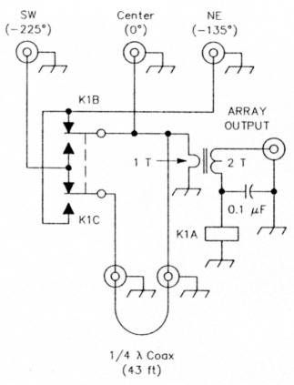
Fig 5 - The feed box includes relay switching to reverse the array's pattern. The 1/4-wavelength RG-58A section shown is essential and works in conjunction with the feed-line lengths shown in Fig 3 to provide proper element phasing. The phase angles shown are for normal operation (northeastern pattern, K1 off); energizing K1 flips the pattern to the southwest by phasing the northeastern loop at -225° and the southeastern loop at -135° relative to the center loop. The transformer (turns ratio, 2:1) is constructed similarly to the 7:1 units used in the loop; see text.
Equal lengths of RG-58A coax run from the feed box to the front and rear elements. These cables are 3/8 wavelength long, plus 2 feet. The center element is fed through 2 feet of cable, thus resulting in a differential phase between the center and end elements of 135°. (Assuming that the cables operate at a low SWR, this technique can be used in other phased-array designs where a ¼-wavelength coax is too short to span the physical distance between elements.) Then insert a ¼-wavelength piece of coax (with RG58A, 43 feet at my array's design frequency of 3795 kHz) in series with the rear element to give a total delay of 225°. A 2:1 ferrite-core transformer matches the three paralleled feed lines to 50 Ω in the feed box.
Adjustment and Measurements
Computer modeling shows virtually no coupling between the loops, so each can be tuned to resonance while ignoring the others. A sensitive SWR meter or return-loss bridge should be used to adjust the variable capacitor for the best impedance match - that is. minimum reflected power or highest return loss. Adjust the loop trimmer via a long, nonmetallic shaft or large plastic knob. Be careful not to get RF burns from the capacitor - high RF voltages appear across it even with only a few watts applied to the loop.
The loops give less than 1.09:1 SWR (a return loss of 27 dB) when fed via 7:1 transformers. The first three-element array I built used 6-dB attenuators in the feeds to the 1st and 3rd elements to set those elements' current at half that of the center element. After the loops were tuned and hooked to the feed box, a front-to-back ratio (F/B) of 25 dB was measured without further adjustment.
The second three-element array I built used series-resistor feed (Fig 6) to enable precise adjustment of the element current. I varied the outer elements' feed-transformer turns ratio to set their current; then added resistors to bring their input impedance up to 50 Ω. (The resistors also add 7 dB of loss.) I adjusted this array for maximum F/B using a remote test signal. The element trimmers can be used for fine adjustment of the element phase. (If you can't adjust your antenna with a remote test signal, use 7:1 transformers at all three elements and set the outer elements' currents with 6-dBpads. A 25-dB front-to-back ratio is well worth achieving at 75 meters!)
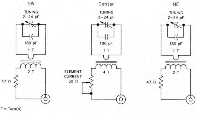
Fig 6 - This alternative feed method uses noninductive series resistors and 2:1 and 4:1 matching transformers to allow precise adjustment of element currents for improved frontto-back ratio. Careful adjustment of this system has achieved a peak improvement of 20 dB over the simpler feed method shown in Fig 3. Fig 7 plots its front-to-back ratio versus frequency.
Fig 7 plots the system's measured front-tohack ratio using series-resistor feed. I consider this performance to be well worth the effort necessary to achieve it.
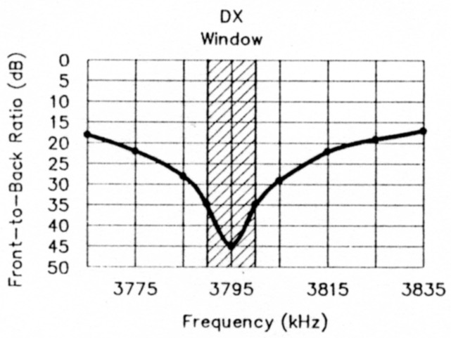
Fig 7 - Adjusted for peak performance at 3795 kHz using the feed method shown in Fig 6, the three-element loop array provides a front-to-back ratio of at least 35 dB across the 75-meter DX window.
Notes
- MN 4.0 by Brian Beezley, K6STI.
- J. Kraus, Antennas (New York: McGraw-Hill, 1950), pp 90-97 and 510.
- H. Jasik, Antenna Engineering Handbook, 1st ed (New York: McGraw-Hill, 19), pp 5-20 to 5-28.
- W. L. Weeks, Antenna Engineering (New York: McGraw-Hill, 1968), pp 84-97.
- J. Devoldere, Low-Band DXing (Newington: ARRL, 1986).
- T. Hart, High Efficiency Antennas alias The Loop(Melbourne, FL 32902: W50JR Antenna Products).
- Transformer assembly #CN20-AT8, manufactured by Ceramic Magnetics, 16 Law Dr, Fairfield, NJ 07004, tel 201-227-4222, fax 201-227-6735. Attn: Jim Florance.
- W. Hayward and D. DeMaw, Solid State Design for the Radio Amateur (Newington: ARRL, 1986).
WA2WVL, Floyd Koontz.