Home - Techniek - Electronica - Radiotechniek - Radio amateur bladen - QST - The lure of the ladder line
I was feeding a short, limited-space antenna with coaxial cable. Everything seemed to be okay, but was it?
Like many hams, I live in a home that's inhospitable to antennas. My house sits on a 100-foot square lot with trees along the back. I always hoped to be the proud owner of a tower and an HF beam antenna, but that was out of the question. What about a vertical? Well, I'd have to bury plenty of radial wires in the rocky Connecticut turf. That didn't sound like fun. I could buy a vertical that didn't require radials, but those antennas were a bit out of my price range and their awkward, spiky appearance didn't blend well with the landscaping. A wire antenna seemed to be the ideal candidate.
Hanging a wire between two trees wasn't a problem, but there was still the aesthetic issue to consider. As much as I love ham radio, I didn't want to arouse the anger of my wife and neighbors by installing a copper monstrosity that looked as if it was spun by a mutant spider. All I wanted was a simple, low-profile dipole that I could operate on a number of HF bands.
Perhaps I could string up a single dipole and feed it with coaxial cable, using an antenna tuner to load it on several bands. The length of the antenna wouldn't be critical. I' d put up as much wire as possible and let the tuner worry about transferring power to the system. Even under high SWR conditions, where lots of energy is reflected back and forth between the tuner and the antenna, a substantial amount of RF would still be radiated. That sounded fine to me.
I put up a 66-foot dipole and fed it with low-loss coaxial cable. Sure enough, my antenna tuner was able to load it on all bands from 40 through 10 meters more or less. The tuner balked a bit on 17 meters and it was very touchy on 10 meters. (Sometimes it arced with a startling snap!) Despite the problems, I used my system to work 75 new countries in just a couple of months, finally clinching my DXCC award. I also enjoyed many stateside contacts.
The SWR was quite high on most bands. At 100 watts output, however, the heavy-duty coax withstood the mismatch without noticeable heating. (I'd certainly notice it at higher power levels, though!) The antenna looked great and seemed to be performing well. Even so, I knew I was losing power in the cable and I wondered how it was affecting the overall performance.
While considering the alternatives, my thoughts drifted to trap dipoles. Yes, a trap dipole can be resonant on several HF bands,but the coil-and-capacitor traps tend to be bulky and prone to loss. How about a fan dipole? Simply attach several resonant dipoles to the same center point and feed them all with one cable. Too big and ugly! (We're back to the spider-web problem again.)
How Bad Can it Be?
I allowed my thoughts to drift for more than a year until I met Dean Straw, N6BV, our new Senior Assistant Technical Editor here at League Headquarters. Dean's field of expertise is antennas and propagation, so I peppered him with questions about my antenna situation.
Yes, he said, my original assumption was correct. A nonresonant antenna will work even with sky-high SWR if the feed-line loss is low enough. My cable provided a low loss. The ARRL Handbook chart indicated that its loss was less than 1.5 dB per 100 feet at 100 MHz. I was only using 50 feet and my highest operating frequency was 29.60 MHz. (Cable loss decreases as feed-line length and frequency decrease.) So how bad could my losses be?
Very bad!
I made the mistake of underestimating the loss under high SWR conditions. Dean used a computer program to calculate the loss on various HF bands when used with my 66-foot dipole. You can see the results inthe middle column of Table 1.1 was shocked, to say the least! My 100-watt signal was reduced substantially on some frequencies. (The higher the dB figure, the more power is lost in the cable. A 3-dB loss represents a 50% reduction.)
Since I insisted on sticking with a single-dipole design, Dean suggested that I replace my coaxial cable with ladder line. Unlike coax, where one conductor completely surrounds another, ladder line places both conductors in parallel. Insulating material is used to maintain a consistent separation. As a result, the fields radiated by the conductors cancel each other and the line is balanced. In 450-ohm line, sections of insulating plastic give the cable a ladder-like appearance, hence the name (see Fig 1).
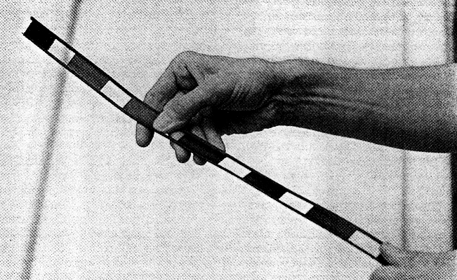
Fig 1 - This type of 450-ohm ladder line uses plastic insulating material to maintain a consistent separation between the two conductors. The air gaps between the Insulation gives it Its ladder-like appearance. Other types of open-wire line are available, but 450-ohm ladder line is the most common.
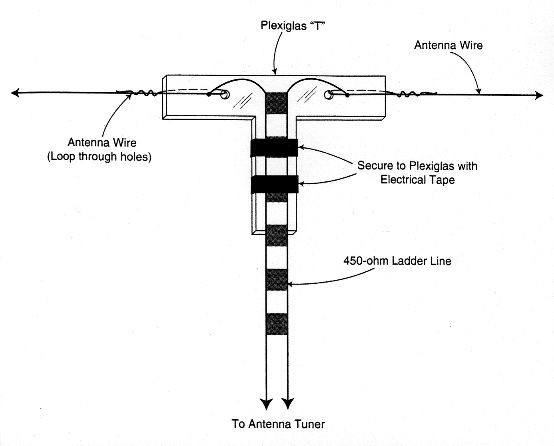
Fig 2 - You can use a piece of Plexiglas to reinforce the ladder-line connection at the antenna. The Plexiglas acts to reduce the flexing of the wires where they connect to the antenna.
"Oh, no," I said. "I know all about ladder line. It radiates RF in your house and you have to keep it away from metal or it won't work."
Dean simply smiled. He ran the loss calculations again, but this time he substituted ladder line (see the right-hand column of Table 1). Wow! On 40 through 10 meters, the loss hardly exceeded 0.3 dB. Now he had my attention. But what about all those ladder-line problems?
"If the ladder line is balanced, it doesn't radiate RF," he replied. "As far as metal objects are concerned, you need to keep the line a few inches away from big sections of steel, aluminum and so on. The fields around the conductors can couple to metal and this creates an imbalance. Unless you intend to tape the ladder line along your gutters, however, I wouldn't worry about it. Your tuner should be able to handle any imbalance that occurs."
| Frequency | Loss (in dB) | |
|---|---|---|
| (MHz) | 8214 | Ladder line |
| 1.9 | 26.9 | 8.62 |
| 3.8 | 13.7 | 1.37 |
| 7.15 | 0.19 | 0.07 |
| 10.14 | 2.85 | 0.07 |
| 14.27 | 5.30 | 0.15 |
| 18.14 | 6.96 | 0.31 |
| 21.40 | 0.78 | 0.12 |
| 24.90 | 3.94 | 0.13 |
| 28.50 | 5.69 | 0.18 |
Cable length: 50 feet.
Antenna: 66-foot dipole at a height of 30 feet.
Calculated by Dean Straw, N6BV, Senior Assistant Technical Editor
The Test
I was determined to put Dean's statements to the test. I purchased a 100-foot roll of 450-ohm ladder line and attached it to the center of my dipole. Since this was a temporary installation, I routed the line across the roof and into the window of my radio room. Along the way I passed over a couple of gutters, across some chimney flashing and along some aluminum siding to my window, which was equipped with metal sashes!
After attaching the line to the balanced-antenna posts on my tuner, I fired up the radio. "This will never work," I mumbled.
The tuner loaded easily on 40 meters, but that proved nothing. The antenna was resonant on 40 meters anyway. I started moving up, band by band. Each time, the tuner reduced the SWR at the transmitter to a flat 1:1 match without difficulty. No arcing. No RF interference. I was stunned!
On 15 meters, I heard a pileup centered on a station in the Marshall Islands. I grabbed the microphone and announced my call sign when he said, "... standing by for calls." He answered me on the first attempt!
"I know what I'll do," I said with a fiendish laugh. "I'll load the antenna on 80 meters. It's way too short to load on 80!"
Wrong again. The tuner quickly brought the SWR down to 1:1. I then proceeded to make several contacts and received outstanding signal reports. This was the first time that I was ever able to use my dipole on 80 meters. I tried 160 meters, but that was pushing it a bit too far for the tuner. A muffled frying sound indicated its displeasure.
The performance of the antenna fed with 450-ohm ladder line has been excellent on all bands. As you might guess, the improvement is most dramatic on the bands where the SWR is highest. Thanks to ladder line, the vast majority of my output power is now radiated at the antenna, not lost in the feed line.
Not a Cure-All
It's important to point out that my nonresonant dipole is a compromise solution designed for the restrictions at my home. The ladder line isn't magical. It simply allows a mediocre antenna to perform much better than it might otherwise. I must keep my output below 150 watts or risk dangerously high RF voltage levels on the feed line (now you know why the tuner arced on 160 meters!). Some antenna tuners may arc even at relatively low power levels. If you decide to attempt this type of antenna design, I recommend a heavy-duty antenna tuner rated at 1 kW or higher. The tuner must provide a balanced output (not all tuners do).
Of course, if I had a resonant antenna instead, I could go back to my low-loss coaxial cable and enjoy equally good performance. I probably wouldn't need an antenna tuner and I could run much more power.
Ladder line can be affected by weather. (Ice, water or debris between the conductors can upset the balance.) Unless you reinforce the connection at the antenna (see Fig 2), the line is likely to break rather quickly. And ladder line can be difficult to locate. (If your local dealer doesn't sell it, check the advertising pages of QST for wire and cable suppliers.) These disadvantages notwithstanding, ladder line is an excellent choice for almost any kind of HF antenna. Not only is it inexpensive, the loss figures at HF frequencies are very low.
Apartment and Condo Dwellers
If you're an apartment/condo dweller, or anyone else suffering under antenna restrictions, ladder line may offer a way for you to get on the air. If you have an attic, for example, install the longest dipole you can and feed it with ladder line. Don' t worry about the length of your antenna. Just make sure that both sides are equal. Use your antenna tuner and determine on which bands you can achieve a 1:1 SWR. You may be surprised to discover that you can become active on at least some HF bands after all!
WB8IMY