Home - Techniek - Electronica - Radiotechniek - Radio amateur bladen - QST - Key components of modern receiver design 3
In this concluding installment, we see how some of today's best amateur transceivers compare with one of today's latest commercial radios in terms of second- and third-order IMD, and how we can make our radios better.
In the preceding two parts of this article, I have covered dynamic range, AGC and synthesizer concepts that are important in high-performance MF/HF reception, and offered some practical circuits for implementing these ideas. In this, the third and last installment, we investigate how the strong-signal performance of today's MF/HF transceivers can be im proved, and compare the performance of a recent commercial counterpart.
Applying These Concepts to Commercial Transceivers
During a recent trip to Germany, I installed my favorite Hustler mobile antenna system (a combination of the MO-I and RM-40) on the aluminum railing of my 19th-floor hotel window in the Munich Sheraton. This translates into an elevation of 180 feet above ground level, and among other things provides a spectacular view of Munich. With the Hustler antenna adjusted for resonance at 7.075 MHz (-3 dB bandwidth, 50 kHz), I scanned the 40-meter band with my TS-450S soon after sunset. Despite the antenna's short length-about 2 meters-incoming signals immediately overloaded the TS-450S's receiver. The radio's speaker put out nothing but noise, and its S meter indicated a minimum of S9 as I scanned 40 meters-yet I could recognize no amateur signals whatsoever! Only strong broadcast stations above 7.1 MHz-"strong" meaning 50 to 60 dB over S9-were clearly detectable. The receiver became marginally usable for weaker signals only after I turned on its 20-dB attenuator and its "AIP" feature. Using the same antenna (still resonant on 40 meters) for 20-meter reception with no input attenuation, I could hear several "ghost" broadcast stations (meaning that I found, on several frequencies, signals apparently carrying two different voice transmissions, one English and one Russian, with music from a third station superimposed on them.) These signals immediately disappeared-plunged from S9 to nothing-when I turned on the TS-450S's 20-dB attenuator. Switching from the 40-meter antenna to a properly tuned 20-meter mobile antenna also made these spurious signals disappear.
Despite recent advances in transceiver design, even the users of high-end transceivers, such as the IC-781, IC-765, TS-950SDX and FT-1000, sometimes find strange mixing products that in no way correlate with intermod measurelilents and calculations appropriate for third-orderIMD prediction. Readers of the first two parts of this article have probably already realized that these products come from second-order IMD. A typical frequency relationship involved in real-life second-order IMD is 6 MHz + 8 MHz = 14 MHz. In this case, 49-meter broadcast signals mix with signals from the fixed or maritime mobile services near 8 MHz, generating ghost broadcast signals every 5 or 10 kHz in the 20-meter amateur band. My experience with my TS-450S and balcony-mounted mobile antenna clearly show that a good-quality transceiver can get into trouble with second-order IMD even when using a fairly small antenna in a good location.
Improving Amateur Transceiver IMD Performance
In earlier parts of this article, I discussed switching-diode characteristics with emphasis on good second-order-IMD performance. To prove that installing PIN diodes in place of a radio's stock front-end-filter switching diodes can improve its secondorder-IMD performance, I modified an ICOM IC-765, had Amateur Electronic Supply modify a Yaesu FT-890, and had Kenwood modify a TS-50 for me.(13) I measured the following results (all tests done at 14 MHz with preamp off, unless otherwise noted):
- The IC-765's second-order intercept increased from +60 to +95 dBm, and its third-order intercept point improved by 6 dB (to about +30 dBm).
- The FT-890's second-order intercept increased from 63 to 93 dBm, and its third-order intercept point increased from +20 dBm to +26 dBm.
- Unmodified, my TS-50 exhibited a second-order intercept point of approximately +35 dBm. Installing PIN diodes improved this to +48 dBm. Using the radio's optional external antenna tuner, which has a peaked high-pass characteristic, improved the second-order intercept point still further, from +85 to +90 dBm. (With two -20 dBm test tones, one at 3.5 MHz and the other at 3.6 MHz, and listening at 7.1 MHz, the TS-50's second-order intercept point is only +30 dBm because the diodes' IMD products become stronger as frequency decreases. With the tuner activated, they disappear.) Installing the PIN diodes also increased the TS-50's third-order input intercept point from +12 to +18 dBm.
- With its original front-end switching diodes in place, my TS-450S exhibited a second-order intercept point of +55 dBm. Reconfiguring the TS-450S's antenna tuner to operate in receive as well as transmit pushed its second-order intercept to about +81 dBm. Replacing its stock switching diodes with PIN devices increased the TS-450S's second-order intercept point to +60 dBm, while its third-order intercept point went from +22 dBm to 28 dBm. Operated from the same hotel with the same balcony-mounted antenna I mentioned earlier, the modified TS-450S exhibited none of the overloading problems it had exhibited before modification.
I believe that the second-order-IMD numbers for the IC-765 and FT-890 after modification are slightly higher because we also modified their antenna tuners to work in transmit and receive. (The inboard antenna tuners in today's Amateur Radio transceivers arc usually in line only in transmit to avoid tuner hunting during split-frequency operation. Because tuner selectivity can directly improve a receiver's second-order IMD dynamic range, I urge equipment manufacturers to build in the option of using our radios' tuners in receive mode.)
I also evaluated a Collins KWM-380 (second-order intercept, +60 dBm), an unmodified TS-950SDX (second-order intercept, "+62 dBm), an unmodified Ten-Tee OMNI VI (second-order intercept, +43 dBm) and finally an unmodified FT-1000 (second-order intercept, over +70 dBm). The TS-950SDX and the FT-I000 tested both included antenna tuners (transmit mode only) and stock switching diodes.(14)
How a Current Professional Transceiver Compares
With second- and third-order-IMD numbers for current high-end Amateur Radio transceivers in hand, it's time to look across to one of our radios' newest military/commercial relatives to see how good "good" radio performance can be. Then we can challenge Amateur Radio equipment manufacturers-who, quite understandably, operate under considerably tighter cost constraints than producers of professional/military radios-to find ways of working toward that performance in Amateur Radio products.
The new Rohde & Schwarz XK2100L, an MF/HF transceiver with receiver coverage from 10 kHz to 30 MHz, implements all of the design concepts discussed in this article. Software menus, not front-panel buttons and knobs, access most of its control functions. The title graphic shows part of the radio's control-menu structure.
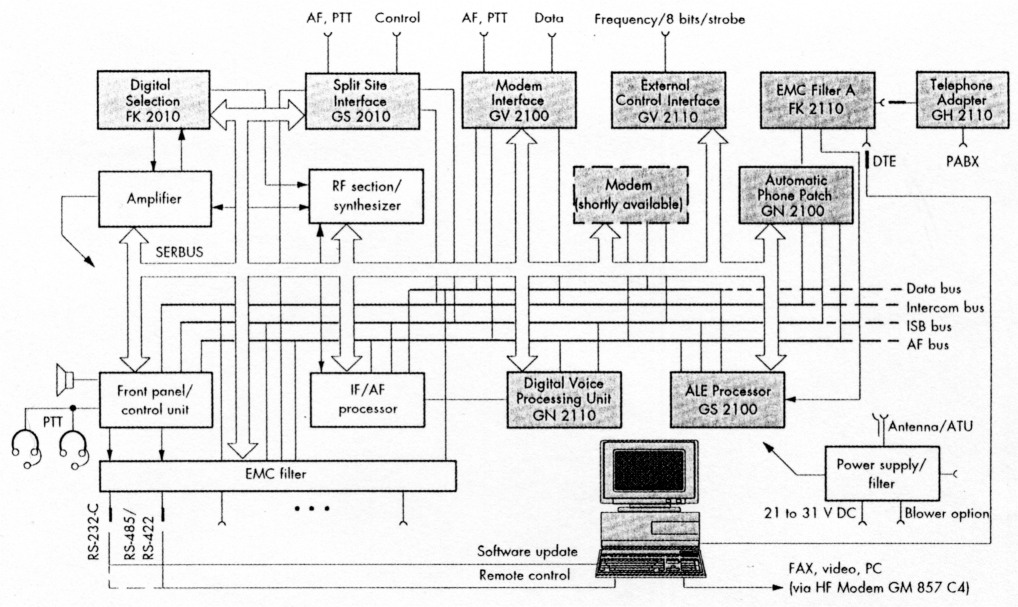
Figure 20-All of the XK2100L's modules use the Rohde & Schwarz SERBUS for control. Shaded modules are options.
Figure 20 diagrams the XK2100L's internal architecture. Like a personal computer, the XK2I00L controls and communicates with its system modules via an internal bus (the Rohde & Schwarz SERBUS). Unlike current amateur MF/HF transceivers, which require the installation of new ROMs or EPROMs for firmware upgrades, the XK2100's operating firmware can be updated with a PC via its RS-232-C interface.
Digital signal processing (DSP) handles all of the XK2I00L's radio's modulation and demodulation functions at IF and AF, allowing:
- A variety of emission classes, such as AME,(15) CW, SSB (USB and LSB), ISB (two indepepdent sidebands), FM, FSK and AFSK (the deviation/shift and baud rate of which can be optimally matched in receive)
- 11 bandwidths from 150 Hz to 8 kHz, with group-delay-equalized filtering for data transmission
- Five AGC decay time constants from 25 ms to 3s
- Passband tuning (with bar-graph pass-band indication)
- An IF notch filter (with bar-graph notch position indication)
- A noise blanker that automatically adapts to the interference's pulse repetition rate and pulse width
- Syllabic squelch (no threshold setting necessary)
- Voice compression that approximately doubles the transmitter's average output power during voice transmission
The XK2I00L's receiver typically exhibits intercept points of +70dBm (IP2) and +35 dBm (IP3), and 10% cross-modulation with an interference source of +20 dBm. Its 9-dB noise figure affords good reception even with short rod or whip antennas, and it can withstand antenna-terminal overvoltages up to 100 V EMF indefinitely. An optional digitally controlled preselector can be installed to provide a -20 dB frontend bandwidth equal to ±10% of the operating frequency. This preselector is in line during transmit and receive, and its tuning time is 20 ms.
On the transmit side, the XK2100L operates at 150 W (PEP SSB) and 100W (CW mode), and supports automatic link establishment (ALE) in line with FED-STD 1045. Properly configured, the transceiver can act as a remote telephone link with all the amenities of a modern telephone set.
Table 2 shows selected XK2100L technical specifications for comparison with those of amateur transceivers. This raises the obvious question of cost. The simple answer is that a basic XK2100L without options sells in the $18,000 range. The useful answer is that I believe that strong-signal RF and AGC performance comparable to that of transceivers like the XK2100L can be achieved for amateur-market prices through more stringent system design. As an example of this, consider that, per QST Product Review testing, the ICOM IC-761 transceiver achieved a third-order intercept of +5 dBm at 20 meters (preamp on),(16) while a Kenwood TS-830S, designed over a decade earlier, achieved an input intercept of -5 dBm at 20 meters (preamp not defeatable)(17) - yet both radios use first mixers consisting of two 2SK125 JFETs. Being given the option of switching out an RF preamp is another aspect of progress: Switching off the preamp in the QST Product Review IC-761 increased its third-order intercept from +5 dBm to +21 dBm at 20 meters.
| General | ||
|---|---|---|
| Switchover times TX/RX, RX/TX | < 10 ms | |
| Frequency Change | < 30 ms | |
| Receiver | ||
| Input Impedance | 50 Ω, VSWR < 3 | |
| Noise figure without preamplifier | 17 dB | |
| Noise figure with preamplifier | 9 dB | |
| Input sensitivity (for S/N of 10 dB from 0.2 to 30 MHz), without preamp | ||
| A1A (CW) | 0.4 µV EMF (-121 dBm), BW = 300 Hz | |
| J3E (SSB) | 1.0 µV EMF (-113 dBm), BW = 2.7 kHz | |
| H3E (AME), 60% mod by 1 kHz | 2.7 µV EMF (-104 dBm), BW = 6 kHz | |
| With preamp | ||
| A1A (CW) | 0.15 µV EMF (-130 dBm), BW = 300 Hz | |
| J3E (SSB), J7B | 0.4 µV EMF (-121 dBm), BW = 2.7 kHz | |
| H3E (AME), 60% mod by 1 kHz | 1.0 µV EMF (-113 dBm), BW = 6 kHz | |
| Receiving bandwidths | -3 dB | -60 dB |
| 150 Hz | 300 Hz | |
| 300 Hz | 450 Hz | |
| 600 Hz | 860 Hz | |
| 1 kHz | 1.54 kHz | |
| 1.5 kHz | 1.98 kHz | |
| 2.1 kHz | 3.2 kHz | |
| 2.4 kHz | 3.52 kHz | |
| 2.7 kHz | 3.8 kHz | |
| 3.1 kHz | 4.2 kHz | |
| 6 kHz | 8.4 kHz | |
| 8 kHz | 10.4 kHz | |
| AGC | < 3 dB output change over the range 1 µV to 1 V EMF | |
| Response to 60-dB step variation | ||
| Attack | <10 ms | |
| Decay | 25/150/500 ms, 1 s/3 s | |
| AF distortion | ||
| Line output, 0 dBm | < 1% | |
| Headphones, loudspeaker | < 10% at rated power | |
| Blocking | 3-dB signal attenuation (Af = 30 kHz, desired signal 2 mV EMF, interfering signal 5 V EMF) | |
| Desensitization | > 20 dB SINAD (M = 30 kHz, BW = 2.7 kHz, desired signal 30 µV, interfering signal 100 mV) | |
| Intercept point (IP3) | > 30 dBm (Af > 30 kHz, interfering signals 2 x 0 dBm) | |
| Cross-modulation | < 10 % (Af > 30 kHz, desired signal 1 mV EMF, 1 kHz, m = 30%) | |
| Inherent spurious signals | < -113 dBm, with few exceptions | |
| Immunity to interference (Δf > 30 kHz) | ||
| Image-frequency rejection | > 80 dB, typically > 90 dB | |
| IF rejection | > 80 dB, typically > 90 dB | |
| Oscillator reradiation | < 10 µV (at antenna input) | |
| Protection of receiver input | up to 100 V EMF (f < 30 MHz) | |
| with digital preselector | up to 200 V EMF (f < 30 MHz) | |
| Transmitter | ||
| Spurious suppression | > 70 dB, typically > 80 dB (into 50 Ω) | |
| Harmonic suppression | > 45 dB, typically > 60 dB (into 50 Ω) | |
| Intermodulation products (with two-tone modulation and 26.5-V supply voltage) | > 32 dB down, typically > 36 dB (referred to PEP) | |
| S/N ratio | > 150 dB, referred to 1-Hz test bandwidth, Δf>1MHz | |
| > 165 dB with digital preselector option | ||
| Carrier suppression | > 60 dB referred to PEP, typically > 70 dB | |
| with voice compression | > 30 dB | |
| Suppression of unwanted sideband | > 60 dB referred to PEP | |
Summary
In this three-part article, I have described an integrated system approach for improved AGC, better selectivity and much-simplified frequency synthesis in MF/HF receivers and transceivers. Considerable better phase-noise performance should be achievable for little, if any, cost increase over that of circuitry already present in our transceivers.
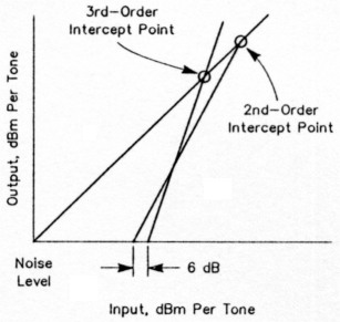
Figure 21-As the levels of input signals rise, second-order IMD products emerge from the noise first, and predominate a receiver's IMD products until signal levels rise far enough for third-order products to overtake them. (After Sabin 1981; see Note 8)
The importance of good second-order IMD performance may be this article's most controversial finding. Figure 21 shows how second-order IMD can be more important than the third-order IMD products: As input-signal levels rise, second-order products emerge from the receiver noise first. Minor changes in input signal level, coupled with falling conditions, can therefore allow second-order products to predominate in some circumstances. Equipment manufacturers listened when radio amateurs asked for receivers with better third-order-1MD performance; now, we must work with them to minimize second-order IMD.(18)
The measurements I've presented show that replacing an amateur transceiver's front-end-filter switching diodes with PIN devices can significantly improve secondorder-IMD performance, but innovation is still necessary in the area of input selectivity, possibly using electronic tracking filters. Even current high-end professional radios need highly selective sub-octave input filtering to achieve the maximum possible second-order intercept point. Being able to use our transceivers' antenna tuners in receive as well as transmit would be one step in the right direction.
Finally, a glimpse at a new commercial-grade MF/HF transceiver confirms that the latest professional/military radios are already implementing IF selectivity digitally, by means of DSP, while simplifying user interface through the use of multilevel menus rather than a forest of knobs, switches and buttons. Studying this radio's technical specifications suggests that state-of-the-art strong-signal and AGC performance may be within reach at amateur-market prices-if we are willing to forgo standard techniques in favor of the new.
Notes
- This procedure was complicated because the TS-50 and similar units from Kenwood use diodes in special SMD packages. I thank the managers at the Siemens Semiconductor Group for making custom diodes available for this test by taking standard 4-µs minority-carrier-lifetime diode chips and packaging them in the appropriate configuration.
- The considerable variation in IP2 among the unmodified radios tested is surprising because all use similar switching diodes. One possible reason for this is that some radio designs, such as the FT-1000, may bias their diodes more optimally than others.
- AM equivalent (full-carrier SSB, or H3E). 16B. Schetgen, ed, The ARRL Radio Buyer's Sourcebook, 1st ed (Newington: ARRL, 1991), pp 2-37 to 2-42.
- B. Schetgen, ed, The ARRL Radio Buyer's Sourcebook, 1st ed, pp 2-89 to 2-92.
- For details on how to calculate IP2 and IP3, see U. Rohde, "Testing and Calculating Intermodulation Distortion in Receivers, QEX, Jul 1994. r-71
KA2WEU, Dr. Ulrich L. Rohde.