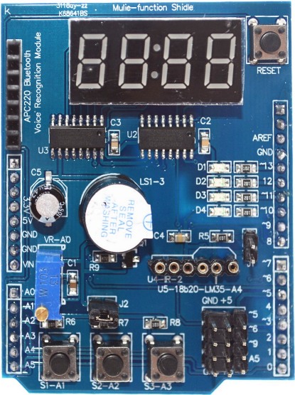
Multi function shield
![]()
Alvorens de mfs op de uno te plaatsen eerst de pinnen van het display zo kort mogelijk afknippen en isolatie over de usb connector plakken i.v.m. mogelijke kortsluiting.
Kenmerken
- 4 digit 7 segment display
- 4 × SMD-leds in parallelschakeling
- 10 K trimpotentiometer
- 3 × drukknoppen
- piëzo zoemer
- IR-ontvangerinterface
- DS18B20 en LM35 interface
- 4 × sensorinterface
- APC220 seriële interface
- Reset knop
Led display
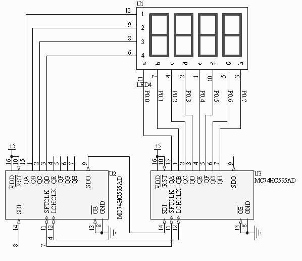
Schema display module.
| Pin | Function | Discription | |
|---|---|---|---|
| 4 | LCHCLK | Latch clock | active low |
| 7 | SFTCLK | Shift clock | active low |
| 8 | SDI | Serial data in |
De aansturing is gemultiplexed.
| a | b | c | d | e | f | g | h | HEX | index | |
|---|---|---|---|---|---|---|---|---|---|---|
| - | 0 | 0 | 0 | 0 | 0 | 0 | 0 | 0 | 0x00 | 0 |
| 1 | 1 | 0 | 0 | 0 | 0 | 0 | 0 | 0 | 0x80 | 1 |
| 2 | 0 | 1 | 0 | 0 | 0 | 0 | 0 | 0 | 0x40 | 2 |
| 3 | 0 | 0 | 1 | 0 | 0 | 0 | 0 | 0 | 0x20 | 3 |
| 4 | 0 | 0 | 0 | 1 | 0 | 0 | 0 | 0 | 0x10 | 4 |
| Zonder dp | Met dp | ||||||||||||
|---|---|---|---|---|---|---|---|---|---|---|---|---|---|
| a | b | c | d | e | f | g | dp | HEX | index | HEX | index | ||
| 0 | 0 | 0 | 0 | 0 | 0 | 0 | 1 | 1 | 0x03 | 0 | 0x02 | 16 | |
| 1 | 1 | 0 | 0 | 1 | 1 | 1 | 1 | 1 | 0x9F | 1 | 0x9E | 17 | |
| 2 | 0 | 0 | 1 | 0 | 0 | 1 | 0 | 1 | 0x25 | 2 | 0x24 | 18 | |
| 3 | 0 | 0 | 0 | 0 | 1 | 1 | 0 | 1 | 0x0D | 3 | 0x0C | 19 | |
| 4 | 1 | 0 | 0 | 1 | 1 | 0 | 0 | 1 | 0x99 | 4 | 0x98 | 20 | |
| 5 | 0 | 1 | 0 | 0 | 1 | 0 | 0 | 1 | 0x49 | 5 | 0x48 | 21 | |
| 6 | 0 | 1 | 0 | 0 | 0 | 0 | 0 | 1 | 0x41 | 6 | 0x40 | 22 | |
| 7 | 0 | 0 | 0 | 1 | 1 | 1 | 1 | 1 | 0x1F | 7 | 0x1E | 23 | |
| 8 | 0 | 0 | 0 | 0 | 0 | 0 | 0 | 1 | 0x01 | 8 | 0x00 | 24 | |
| 9 | 0 | 0 | 0 | 0 | 1 | 0 | 0 | 1 | 0x09 | 9 | 0x08 | 25 | |
| A | 0 | 0 | 0 | 1 | 0 | 0 | 0 | 1 | 0x11 | 10 | 0x10 | 26 | |
| B | 1 | 1 | 0 | 0 | 0 | 0 | 0 | 1 | 0xC1 | 11 | 0xC0 | 27 | |
| C | 0 | 1 | 1 | 0 | 0 | 0 | 1 | 1 | 0x63 | 12 | 0x62 | 28 | |
| D | 1 | 0 | 0 | 0 | 0 | 1 | 0 | 1 | 0x85 | 13 | 0x84 | 29 | |
| E | 0 | 1 | 1 | 0 | 0 | 0 | 0 | 1 | 0x61 | 14 | 0x60 | 30 | |
| F | 0 | 1 | 1 | 1 | 0 | 0 | 0 | 1 | 0x71 | 15 | 0x70 | 31 | |
| 1 | 1 | 1 | 1 | 1 | 1 | 1 | 1 | 0xFF | 32 | 0xFE | 33 | ||
| Segmenten | |||||||||||||
| dp | 1 | 1 | 1 | 1 | 1 | 1 | 1 | 0 | 0xFF | 33 | |||
| sa | 0 | 1 | 1 | 1 | 1 | 1 | 1 | 1 | 0x7F | 34 | |||
| sb | 1 | 0 | 1 | 1 | 1 | 1 | 1 | 1 | 0xBF | 35 | |||
| sc | 1 | 1 | 0 | 1 | 1 | 1 | 1 | 1 | 0xDF | 36 | |||
| sd | 1 | 1 | 1 | 0 | 1 | 1 | 1 | 1 | 0xEF | 37 | |||
| se | 1 | 1 | 1 | 1 | 0 | 1 | 1 | 1 | 0xF7 | 38 | |||
| sf | 1 | 1 | 1 | 1 | 1 | 0 | 1 | 1 | 0xFB | 39 | |||
| sg | 1 | 1 | 1 | 1 | 1 | 1 | 0 | 1 | 0xFD | 40 | |||
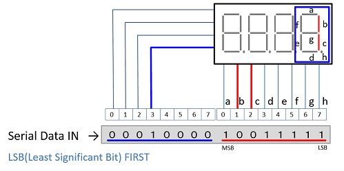
Code
De numMap[] is voor hexadecimaal (0-F) gebruik. Voor gebruik van de decimale punt de tabel uitbreiden in de volgorde van de indexnummers.
const byte numMap[] = {0x03, 0x9F, 0x25, 0x0D, 0x99, 0x49, 0x41, 0x1F, 0x01, 0x09, 0x11, 0xC1, 0x63, 0x85, 0x61, 0x71, 0xFF};
const byte digitMap[] = {0x00, 0x80, 0x40, 0x20, 0x10};
Voor ieder digit run de onderstaande code. Value is de index zoals vermeld in de codetabel.
void dispNum(int digitNum, int Value) {
  digitalWrite(D_LATCH, LOW);
  shiftOut(D_DATA, D_CLK, LSBFIRST, numMap[Value]);
  shiftOut(D_DATA, D_CLK, LSBFIRST, digitMap[digitNum]);
  digitalWrite(D_LATCH, HIGH);
}
Na het aansturen van de vier digits de code met dispNum(0, 32) draaien om te zorgen dat het laatste display niet helderder brand dan de eerste drie.
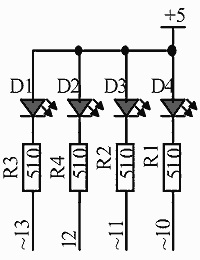
SMD leds
LED gaat branden als de poort laag wordt.
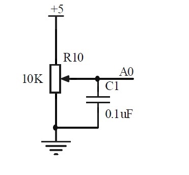
Trimpotentiometer
De loper van de potmeter geeft een spanning tussen 0 en 5 V aan A0.
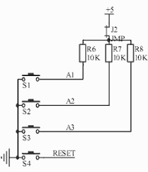
Drukknoppen
De drukknopen S1, S2, S3 zetten 0 V op resp. A1, A2 of A3. In rust is dit 5 V.
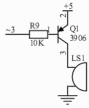
Piëzo zoemer
De zoemer gaat aan als 3 laag wordt.
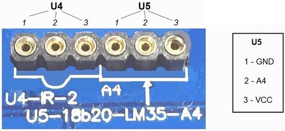
IR ontvangerinterface U4
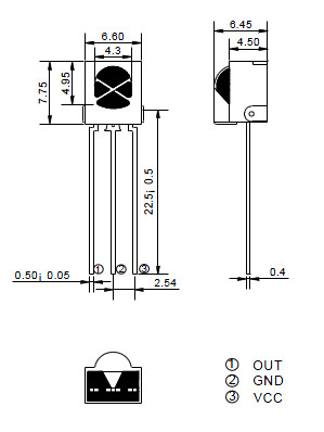
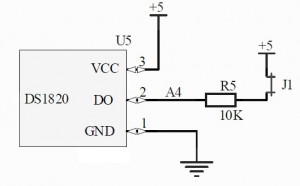
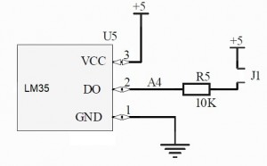
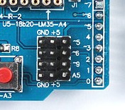
DS18B20 en LM35 interface U5
Sensor en actuator interface
Voor sensor en actuator gebruik zijn de poorten 5, 6, 9 en A5 beschikbaar. De sensoren en actuators worden vanaf hier gevoed met 5 V.
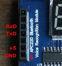
Seriële interface
Programming
Let's define the board to make it easier to program
One of the convenient features of programming in Arduino is that you can define names to represent the Arduino pins. As you program, it is easy to remember that BUZZER is the pin that the buzzer is connected to. We will use a name for each of the features so we can make our code easier to read and write. Here is how we do that:
#define LED_1 13 // LED pins
#define LED_2 12
#define LED_3 11
#define LED_4 10
#define BUZZER 3 // The buzzer
#define IR 2
#define POTMETER A0 // The analog input for the potentiometer
#define BUTTON_1 A1 // The input pushbuttons
#define BUTTON_2 A2
#define BUTTON_3 A3
#define TEMP A4
#define DISP_LATCH 4 // The 3 pins that control the display
#define DISP_CLK 7
#define DISP_DATA 8
If you insert these #define statements in the beginning of your Arduino code, you will now be able to refer to the features by their name instead of their pin number.
Setup
The next thing you usually want to do is set up the pinMode for each of these features. If you are a veteran Arduino programmer, you will have noticed that most libraries will do this for pins the library is going to use. However, it is good practice to ensure the pins are setup to your liking. In your setup() procedure you would want the following pinMode() commands:
First, set the LED pins as outputs:
pinMode(LED_1, OUTPUT);
pinMode(LED_2, OUTPUT);
pinMode(LED_3, OUTPUT);
pinMode(LED_4, OUTPUT);
Write this pins high so they will turn off the LEDs:
digitalWrite(LED_1, HIGH);
digitalWrite(LED_2, HIGH);
digitalWrite(LED_3, HIGH);
digitalWrite(LED_4, HIGH);
Next, set the pushbuttons as inputs (there are pullup resistors on the board so there is no need for the internal pullups).
pinMode(BUTTON_1, INPUT);
pinMode(BUTTON_2, INPUT);
pinMode(BUTTON_3, INPUT);
Set the buzzer as an output:
pinMode(BUZZER, OUTPUT);
And turn it off:
digitalWrite(BUZZER, HIGH);
Set the IR poort.
pinMode(IR, INPUT);
Finally, define the display pins as outputs:
pinMode(DISP_LATCH, OUTPUT);
pinMode(DISP_CLK, OUTPUT);
pinMode(DISP_DATA, OUTPUT);
That finishes our setup for using the board. You can find the full setup code in this sketch. Put your code in the loop.
The library for this shield only works with the UNO and not with others.
Docs
Projecten met de MFS
- Decimale counter
- Hexadecimale counter
- RTC klok met de MFS with the MEGA and the RS3231.
Overige multi function shields
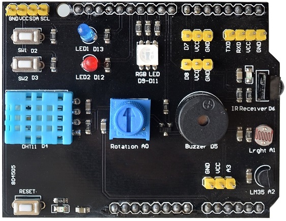
DHT11 - LM35 multi function shield