Inside Voyager
John Wilson looks into the daunting business of running an old spacecraft five light hours away, boldly going where no robot has gone before.
"A truly remarkable spacecraft" is the somewhat understated description by one scientist of the 825kg of hardware that has recently sent us some of the most dazzling pictures we're ever likely to see of our own solar system. It would be a fitting description of 1980s technology, let alone a machine designed in the early 1970s and which has wandered, unserviced, for 12 years through the inhospitable vacuum radiation and wildly fluctuating temperatures of space.
Although Voyager will mainly be remembered for its pictures, it's worth noting that it carries eleven different experiments, each of which undertook hundreds and sometimes thousands of observations each time the craft passed a planet or moon. Designing and positioning these instruments and their power supplies and housekeeping equipment to work without manual interference was therefore as much an achievement as any of the pictures or data that were transmitted the 4.4 billion kilometres back to Earth.
Structure and configuration
The basic structure of Voyager-2, shown in Fig. 1, (and its identical, equally successful sister craft Voyager-1 now also heading off into deep space) is a 29.5kg 10-sided aluminium framework with ten compartments to house electronics packages. These packages also form structural elements of the framework which, overall, measures 1.8m in diameter.
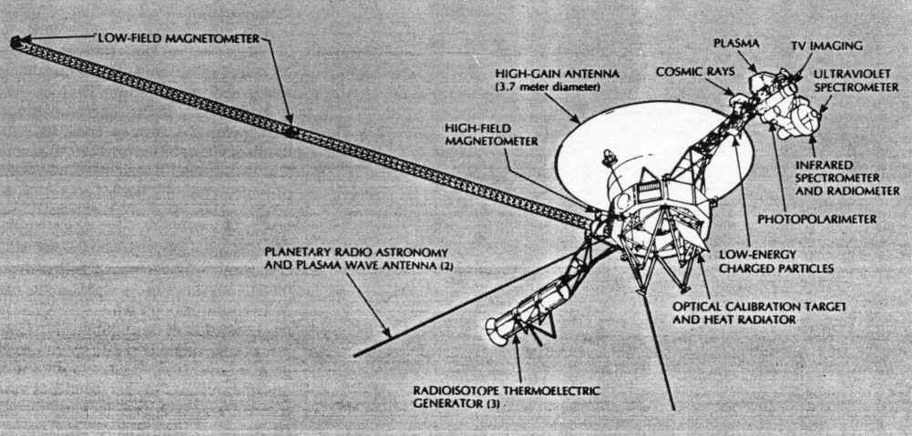
Fig. 1. Sketch of the Voyager spacecraft, showing its main experiments.
Occupying the centre of this decagon below the attached high-gain antenna are 16 small thruster rockets for delicate attitude control manoeuvres as well as for major coi rections to the flight trajectory. Also mounted on this main frame are the Sun sensors (which poke through a hole in the dish antenna) and the Canopus star tracker units which together provide input data for the onboard navigational computer.
Power supply
Yawning one's way through tedious descriptions of DIY AC mains PSUs makes one a little reluctant to describe this function ahead of other electronics systems. Voyager's power supply is somewhat different, however, and not just because of the absence of a plug! Operating in regions of space where the Sun's energy would scarcely melt solid nitrogen, every watt of electricity has to be generated by an entirely self-contained system. Three thermoelectric generators, each weighing 39kg and producing 160W, are assembled on a boom well away from the spacecraft proper, to ensure efficient cooling and avoid problems caused by spurious gamma radiation. Isotopic decay of plutonium 238 provides the heat energy which, when converted into electricity, is expected to provide usable power well into the next century!
Current from the thermoelectric generators is controlled to a constant 30V DC by a shunt regulator and fed directly to some of the spacecraft's subsystems. The reason for the shunt regulator is to provide a constant load on the generators which would overheat if operated open-circuit. A fat resistor dissipates the surplus energy into space. Among the users of the 30V rail are the radio subsystem, the gyros, the control valves, the temperature control system and the antenna deployment motors.
Most of the spacecraft's systems make use, however, of a 2.4kHz square-wave supply derived from the 30V by one of two inverters. A 4.8kHz timing signal derived from the flight data subsystem is used to synchronize this inverter and hence provide Voyager's master clock. Accuracy is ±0.002%.
Apart from these continuous sources of power, Voyager has some novel ways of coping with peaks of power demand. Because no batteries would work for 12 years at -200°C, the Voyager PSU incorporates oversized capacitor banks especially designed to avoid voltage dips during transient surges such as occur when a transmitter PA stage is turned on. Batteries were used during the injection phase of the mission, but jettisoned a few minutes after the craft had left Earth orbit on its trajectory towards Jupiter. Two batteries, each consisting of 22 silver oxide cells, were charged with electrolyte while in space and then used for only 12 minutes to control propellant valves before being junked!
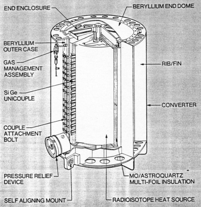
Fig 2. Radioisotope thermoelectric generator, which provides 500W of power to the systems. Most of the power is used by the "housekeeping" operations, relatively little being taken by the experiments.
Computer control system
Apart from mid-course corrrections which require ground control to initiate, all Voyager's control systems are essentially automatic; so much so that a limited mission could have been undertaken if the uplink had failed completely. As it was, most uplink signals were used to trigger pre-programmed sequences of events emanating from the spacecraft's computer command system (CCS). The CCS has two independent plated-wire memories, each with a capacity of 4096 data words. Half of each memory stores re-usable fixed routines while the other halves are re-programmable by updates from the ground. These programmable sequences have proved a vital part of the mission, allowing trajectory changes in the light of new discoveries and also enabling minor technical defects to be circumvented successfully. Such updates have been transmitted from Earth at a data rate of l6bit/s.
Attitude and articulation control system (AACS)
Like the CCS, the AACS includes a re-programmable computer with two independent 4096-word memories. This is fed with data from two redundant Sun sensors, the two Canopus star trackers, three two-axis gyros and, if necessary, ground control. Outputs go to the various onboard rocket motors to maintain _overall spacecraft orientation in three axes and to the actuators driving the science platforms, which carry two tv cameras, a UV spectrometer, a photopolarimeter, an infrared spectrometer and a radiometer.
Maintaining the spacecraft's orientation is vital for three reasons: to ensure it follows the proper trajectory, to maintain communications with Earth and to provide a stable base for visual and other planetary observations. With Voyager (unlike the ill-fated Russian Phobos missions) this works even when communications from Earth are garbled. The Sun sensors stabilize the craft in two dimensions while the Canopus trackers add the third dimension. Canopus is one of the brightest stars in the galaxy and brightness measurements are telemetered to the ground to verify that the trackers have locked on to the correct star! If not (or when Voyager is occulted or deliberately put out of celestial lock), stabilization on three axes can be achieved using just the three gyros. Each gyro has associated electronics to provide positional information about two orthogonal axes.
The science platform referred to above can be rotated about two axes independently of the spacecraft as a whole. This allows panning and precise pointing to within 2.5 milliradians as Voyager whizzes past its target objects at 60 000km/h or more. The platform actuators are fed from driver circuits within the AACS and can be stewed on one axis at a time in response to computer commands. Maximum slew rate is one degree per second.
In 1987 Voyager-2's science platform jammed in one axis just after the encounter with Saturn, though it freed itself after two days. Three years of subsequent analysis and testing showed that the problem was due to a loss of lubricant from over-use at the maximum slew rate. This resulted in damage to a bearing in a high-speed gear train. Fortunately the lubricant apparently migrated back into the gears after a period of rest, allowing the platform to operate successfully (albeit at lower speeds) during the Uranus and Neptune encounters.
Communications
The communications system consists essentially of a pair of S-band receivers operating at 2113MHz, a pair of S-band transmitters operating at 2295MHz and a pair of X-band transmitters on 8418MHz. In actual fact various combinations of exciters and TWT power amplifiers can be `bolted together' as directed by the onboard logic within the CCS. In addition to these, the Voyager communications system carries a modulation/demodulation subystem (MDS), a data storage subsystem (DSS), the low and high-gain antennas and a programmable flight data subsystem (FDS) that controls the scientific instruments and formats all science and engineering data for transmission to Earth on a maximum of 28.3W!
The justification for the extensive redundancy built into Voyager's design was nowhere better demonstrated than in the events of April 5th, 1978. On that almost fateful day the spacecraft's CCS automatically switched to the back-up receiver. The back-up at that point had concealed a problem of its own - a faulty tracking loop capacitor- meaning that the receiver could not lock onto the perceived changes in uplink transmission frequency. This required the ground transmitter to be varied from its nominal 2113MHz to take into account several factors including receiver temperature fluctuations and the Doppler shift caused by the relative motion between the spacecraft and Earth. Voyager engineers have now developed techniques to predict the frequency they need to use, though in desperation they sometimes pepper the sky with commands on a rapid succession of different frequencies!
A full account of the whole communications exercise would be a subject on its own; suffice to say that numerous data rates for each type of telemetered information were required to cope with the changing path lengths, the type of data and various other factors. The flight data subsystem (FDS) handles imaging data from the two vidicon cameras at six different rates varying from 115.2 to 19.2 kbit/s, while the data storage subsystem on Voyager consists of a belt-driven, half-inch, eight-track magnetic tape recorder capable of recording at two speeds and playing back at four. Total recyclable storage capacity is about 536Mbit.
Science investigations
Imaging devices and infrared and UV spectroscopy have already been referred to. Also on board are non-steerable experiments that divide into two basic categories: magnetic and particle detectors and radio and plasma wave investigators.
The first of these senses fluxes and particle fields, not just from the planets but on Sun/planet and planet/satellite interactions. Also, as Voyager heads out of the solar system, these instruments will be taking on increasing interest in cosmic rays and the outer reaches of the solar plasma.
A second family of non-steerable experiments includes radio astronomy and plasma wave investigations. The planetary radio astronomy investigation consists of a stepped-frequency radio receiver that covers 20kHz to 40.5MHz and two 10m whip antennas to study a variety of signals emitted by the planets, notably Jupiter.
Other radio science investigations make use of Voyager's primary communications system to study the effects of the Earth's atmosphere and also of planetary and satellite atmospheres and ionosphere, especially the scattering due to Saturn's rings.
This look at Voyager's housekeeping, communications and experimental equipment has been necessarily brief and omits whole areas of interest such as thermal management, data processing and operating and experimental procedures. It is hoped, though, that this information - all culled from NASA sources - has given some insight into the complex problems of designing and managing a 12-year-old robot in a freezing alien world nearly five light hours from planet Earth.
Research Notes, July 1989, p.648 described the communications package of Voyager in greater detail.