Reducing mast height at MF
One of the major and most costly problems that face all users of the low and medium-frequency spectrum for broadcasting, communications or radio-navigation - as well as radio amateurs using the 1.8 and 3.5MHz bands - is achieving good ground-wave or low-angle sky-wave radiation efficiencies without the use of very high masts or towers and large number of buried radials. For many years a popular form of top-loaded MF antenna has been the so-called "umbrella" design in which a number of drooping radial elements fan out from the single central support, rather like guy wires, to provide top capacitance loading. Such designs do, however, require extremely good earth systems, often taking the form of 120 or more buried radials.
In 1973 Carl E. Smith and John D. Musselman patented a form of umbrella antenna using a counterpoise insulated from earth (US Patent no 3,742,511). This arrangement was used in Vietnam for a navigational system (260 to 535kHz) using a 35ft inflatable mast made by Goodyear; this achieved a radiation efficiency of the order of 67%. In 1974, the Smith-Musselman approach was used for a broadcast station, KVOK at Kodiak, Alaska using a 152ft mast and achieving an efficiency of about 92% at 560kHz.
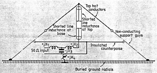
Carl E. Smith has now described (IEEE Trans. on Broadcasting, June 1989, pages 237-240) a modified short low-loss AM antenna and explores ways in which the performance of relatively small transmitting or receiving antenna systems can be improved. He writes: "Small AM antennas are useful for standby use when the regular antenna fails for some reason. With some modification of a short tower by using top loading, low-loss loading inductances and an insulated counterpoise, the performance can be made quite acceptable. The counterpoise is connected as shown in the illustration. The inductance +jx4 is tuned so as to maximise the field strength radiated by the antenna into the far field... Top loading raises the current loop on the tower and, by adding a low-loss inductance at the top of the tower, the current loop is raised still higher on the tower. A low-loss inductance at the top of the tower can be achieved by insulating a suitable conductor inside the tower and shorting it to the tower to simulate a short-circulated coaxial line with the open and inner conductor connected to the top loading hat at the top of the tower... At the bottom of the tower, more series inductance can be added by insulating a conductor up inside the tower to a shorting point. It may also be necessary to add a low-loss base loading-coil to resonate the top hat with the counterpoise... The counterpoise potential is adjusted to minimize ground losses."
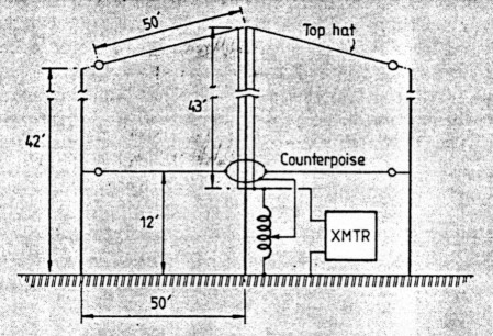
Dr James F. Corum of Corum & Associates Inc. believes that "The Smith/Musselman low-loss tuned-counterpoise structure is a remarkable addition to the technology of electrically-small antennas... it represents a significant contribution to this branch of antenna engineering. We think that anyone requiring a vertical stub with an abbreviated ground system should seriously consider this technology." It is clear from the paper that results are highly dependent upon correct tuning of the counterpoise system, preferably while observing the far-zone field strength. At the Corum test facility at Windsor, Ohio, a Smith/Musselman radiator resonating on 1330kHz had a tower height of 43ft, a top hat of 24 horizontal radials 50ft long, a counterpoise of 24-50 radials 12ft above ground and soil conductivity of 8 millimhos per metre, producing a field strength at 1 mile of 1.1mV/m with 250mW input with the counterpoise tuned, dropping to 605p.V/m without the tuned counterpoise.
Pat Hawker.