The 4 + 1 Tone Decoder
Decoder for both group and individual calls for under $35!
Hams often wish they could shut off all the signals on a busy repeater except the one calling specifically for them. It would be nice to leave the HT on at work without getting fired!
Now they can with the 4 + 1 Decoder. It's smart speaker that plugs into a speaker jack and remains silent until someone activates it with a personal 4 digit DTMF (Touch-Tone(1)) sequence.
The circuit was inspired by the local RACES/ARES emergency group. All the members had 2 meter radios, but few were willing to keep them turned on during the day the office or late at night at home. The solution was to design a circuit that would allow each member to have his own four digit sequence, and also respond to a single command to activate everyone at once.
The 4 + 1 Decoder responds at any time to either a four digit sequence, or one digit sent for three seconds, hence the name "4 + 1 Decoder." Everyone's decoder can be set to the same 3 second (long-tone) for a general call-up. Whether or not the call-up feature is used, each operator can still select a tone sequence up to four digits long for his own personal calling code. For under $35 in parts, is hard to beat.
The idea of using a DTMF decoder to control a radio's speaker is not new, especially for emergency communication(2). There's at least one high quality decoder with speaker available commercially for under $100 (Auto-Kall), and Heathkit offers a kit that can be radily adapted(3). The 4 + 1 Decoder, however, is the first low-cost circuit that allows both individual and group calling.
Typical Operation
DTMF digits are selected with jumper wires in an IC socket. For low cost and simplicity, only digits 1 through 9 and special digit, "D", are decoded. The digits 0, *, #, A, B, and C are not recognized. One digit is selected for the single long tone, and one to four digits are selected for the sequence. A single digit can be used repeatedly.
The only other adjustment is a potentiometer. This is used to preset how many seconds the speaker will be on, once the proper digit is recognized. The decoder is then connected to the radio as an external speaker. The decoder's speaker remains off until it receives the proper digit or sequence. Once triggered, a "call" lamp lights and the speaker is connected to the radio's audio. After the preset period, the speaker is shut off until another valid input reactivates the speaker. There is a bypass switch to defeat the decode function and thus allow the user to listen to all traffic on the frequency. There is also a reset button on the decoder that immediately quiets the speaker and extinguishes the call lamp.
Circuit
Figure 1 is a schematic of the decoder board. U1 is a DTMF decoder chip. It does 90% of the work by recognizing DTMF digits and converting them into binary codes. Since U I uses a "colorburst" crystal and sophisticated digital filtering, its accuracy and stability are superior to decoders made from phase-lock loop tone decoder ICs (e.g., the LM567)(4). U2 converts the binary codes from U 1 into individual signals, one for each digit 1 to 9, and digit D.
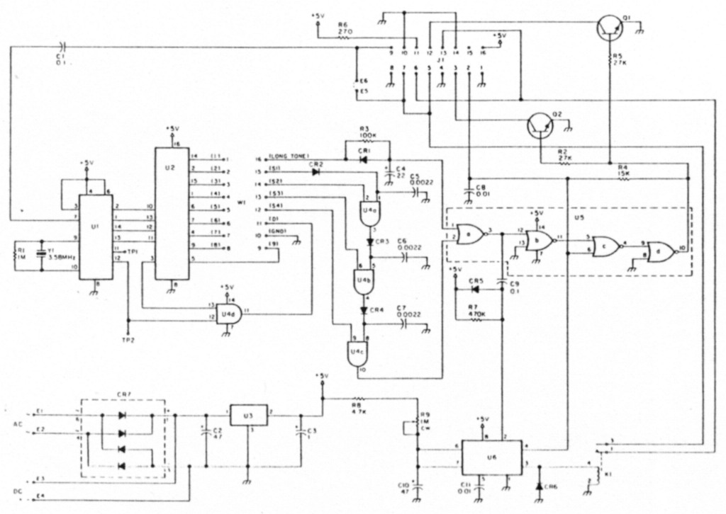
Figure 1. Schematic of decoder circuit.
Sequence Entry
The programming socket allows the user to pick off the digits and send them to U4 for either sequencing or timing. The sequencing method is unusual and is one reason for the low cost. The first digit of the sequence charges C5 via CR2. C5 will hold its charge at one of the two inputs to U4a for about half a second. During this period, the second digit can enable the other input to U4a. Once both inputs to U4a (an AND gate) are active, the output of U4a turns on and charges C6 via CR3. Now one input of U4b is enabled for half a second, while the circuit waits for the third digit in the sequence, to enable the other input to U4b. A successful third digit activates the output of U4b, which this time charges C7 through CR4. If the fourth digit arrives within the next half second, it similarly enable U4c's output. This output activates the call lamp latch (U5) and speaker timer (U6).
Long-tone Timer
The long-tone timer operates on a variation of the sequencer. While the long tone is received, R3 slowly charges C4. If the long tone stops before the three second interval, CR1 (which has the opposite polarity in the circuit as D2-D4) rapidly discharges C4. Once C4 is fully charged by a sufficiently long, uninterrupted digit, the output of U4d is enabled, which triggers U5 and U6.
A successful sequence or single three second DTMF digit starts timer U6 and latches U5. U5 holds the call lamp on. Meanwhile, while U6 is running, relay Kl is energized and connects the speaker to the radio's audio. The reset button resets U5. The reset button also interrupts the timing period of U6.
U4 is the regulator for a versatile power supply which will accept 7-14 volts, AC or DC. Two typical power sources are an automobile cigarette lighter and a modular wall transformer.
Changing Timing
The value of C4 determines the duration requirement for the long tone. Longer times require larger capacitance values. Three seconds, however, proved most practical. The entry speed for sequential decoding is determined by C5-C7. Larger values relax the speed requirement, but increases the possibilty of false triggering from digit sequences similar to the programmed sequence. For example, if the sequence of 6-8-2-1 is sent fast enough, it will trigger a decoder set for the sequence 6-2-1. If false triggers are a problem, decrease values for C5-C7. The speaker timer is controlled by R9 and C10. The values shown allow times ranging from 1 to 60 seconds. Increasing C10 increases this range. Ranges up to 10 minutes are possible.
Programming
Both the long-code and the 1 to 4 digit code sequence are programmed at the programming socket (W 1). The easiest method for programming is to wire a 16-pin IC "header." Wire several headers for quick programming changing. Pins 1 through 9 of the header correspond to DTMF digits I through 9, pin 10 is ground, and pin 11 corresponds to the digit D. To program the long-tone, select a digit and tie a jumper from the corresponding pin number to pin 16. Jumping pin 16 to the ground, pin 10, disables the long-tone timer.
Sequence programming is almost as simple. Wire pin 15 to the first digit of the sequence, pin 14 to the second digit, pin 13 to the third digit, and pin 12 to the fourth digit. If only a 3, 2, or 1 digit sequence is desired, wire the unused sequence pins (12, 13, or 14) to the last digit of the code. For example, when programming the 2 digit sequence 1-2, pins 12, 13 and 14 are all connected to pin 2. Here's a 3-digit programming example.
Header wiring to program Long-tone 5 and sequence 2-7-2:
- Long-tone pin 16 to pin 5 (digit 5)
- 1st digit of sequence pin 15 to pin 2 (digit 2)
- 2nd digit of sequence pin 14 to pin 7 (digit 7)
- 3rd digit of sequence pin 13 to pin 2 (digit 2)
- 4th digit of sequence pin 12 to pin 2 (digit 2)
This example illustrates one important limitation to the sequence programming: The decoder can't differentiate between a single digit and a single digit repeated (e.g. 2 versus 2-2-2). For example, the program sequence 9-l-1 triggers the audio with 9-1.
Power Consumption
The circuit draws 15 mA while waiting for a call, mostly due to U 1. This makes operation from a small (9 volt) battery impractical, so I use a $ 15 motorcycle battery to power the decoder and HT at night. When the relay and LED are energized, the circuit draws slightly over 40 mA.
Construction
Component layout is not critical. Just remeber to keep the connections from U Ito the crystal fairly short, and carefully handle the U2, U4, and U5 CMOS ICs. Either wire-wrap or point-to-point wiring will suffice, but using a printed circuit board is easiest (see using a printed circuit board is easiest (see parts list). The available PC board will hold all the components except LED, speaker, connectors and switches. Most of the connections external to the board (Figure 2) are connected via holes for a 16-pin IC socket 01). One can wire connections either directly to the board or through a header plugged into an IC socket.
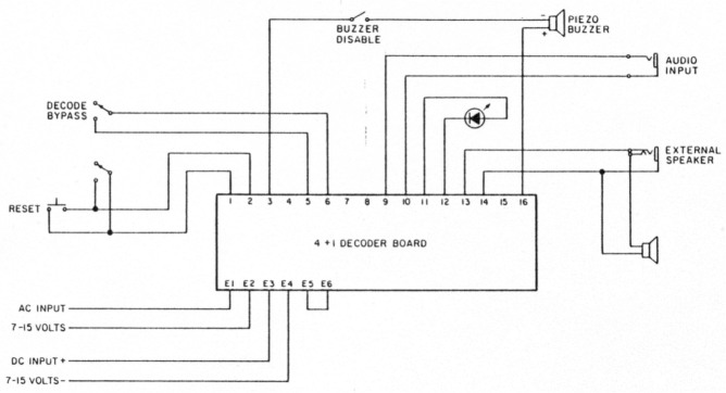
Figure 2. Wiring external to the circuit board. This configuration is for activating an internal or external speaker.
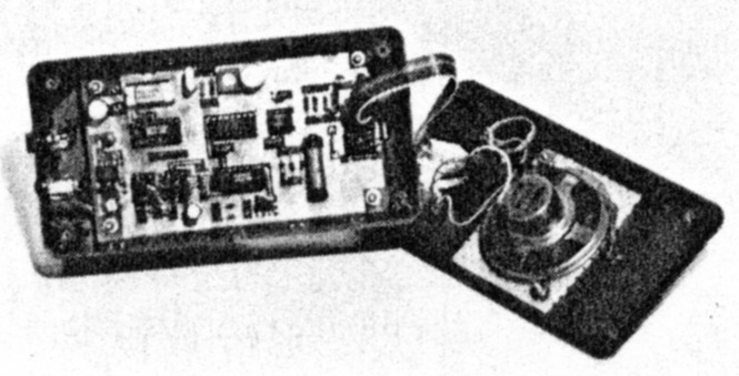
Photo A. Inside view of the completed decoder. The circuit board is on the bottom of the box. A ribbon cable connects the board to the speaker, LED, and switches on the front panel. Jacks for audio input, external speaker output. and power are mounted on the far end of the box. A piezo buzzer (see Figure 2) was not included in this version.
I built the completed unit shown in Photo A into an inexpensive plastic box (see parts list). A hole saw, normally used to cut 1" subminiature toggle (decode/bypass) switch holes or smaller, drilled a speaker hole into the removable lid of the box. A piece of perf board served as the speaker grille. When mounted in the box, the inexpensive 2-inch speaker had remarkably good audio quality. The call LED was mounted just above the speaker using a dab of epoxy to hold it in place. A push button reset switch and a DPST subminiature toggle (decode/bypass) switch are mounted below the speaker. The PC aard sits on metal stand-offs bolted to the bottom of the box, but before the circuit board fit into place, connectors were mounted at one end of the box to accomodate audio input, external speaker, and power. I chose the external speaker jack to match the jack on my rig. (This way, I don't need an adapter to use my external speaker with either rig or decoder.) The audio input jack is a different size to prevent errors. A standard concentric type power jack is the power connection. Ribbon cable connects the circuit board to the jacks, and the circuit board to the top panel. Stick-on rubber feet added to the bottom of case puts on the finishing touch.
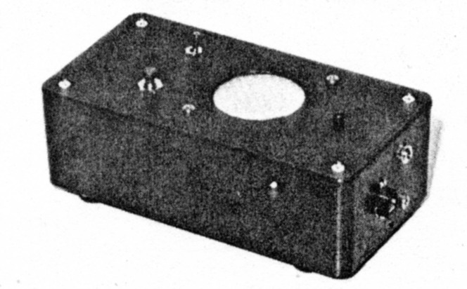
Photo B. The encased tone decoder.
| Circuit board | |
|---|---|
| C1 | 0.1µF |
| C2 | 47µF 16V electrolytic |
| C3 | 1µF 6V electrolytic |
| C4 | 22µF 16V electrolytic |
| C5-C7 | 0.0022µF |
| C8 | 0.01µF |
| C9 | 0.1µF |
| C10 | 47µF 6V electrolytic |
| C11 | 0.01µF |
| CR1-CR6 | 1N914 or similar |
| CR7 | DB101 or VM08 bridge rectifier, or 4 1N4001 diodes |
| K1 | Radio Shack 275-232 miniature 5-volt relay |
| Q1,Q2 | 2N3904 |
| R1 | 1.0MΩ 1/4W 10% |
| R2 | 27kΩ 1/4W 10% |
| R3 | 100kΩ 1/4W 10% |
| R4 | 15kΩ 1/4W 10% |
| R5 | 27kΩ 1/4W 10% |
| R6 | 270Ω 1/4W 10% |
| R7 | 470kΩ 1/4W 10% |
| R8 | 4.7kΩ 1/ 4W 10% |
| R9 | 1MΩ 1-turn trimpot |
| U1 | RCA CDD22204E or SSI 204 DTMF receiver |
| U2 | CD4028B CMOS BCD decoder |
| U3 | 78L05AC low power 5V regulator |
| U4 | CD4081 B CMOS quad AND gate |
| U5 | CD4001 B CMOS quad NOR gate |
| U6 | NE555 timer |
| W1 | 16 pin IC socket and 16 pin header |
| Y1 | 3.579545 Colorburst crystal |
| External to circuit board | |
| Buzzer | Radio Shack miniature piezo buzzer |
| Case | Radio Shack 270-223 (6" x 3.15" x 1.84") |
| LED | regular or flashing LED |
| Power | 8 vdc, 400 mA wall transformer (Jameco DC800) |
| Speaker | 4Ω or 8Ω miniature speaker |
| Switches | SPST normally open momentary switch (reset) |
| SPST miniature toggle switch (buzzer disable) | |
| DPST miniature toggle switch (decode/bypass) | |
Configuration
The board operates from either AC or DC. Board connections E3 and E4 are for + and - connections, especially if a DC source is used. Omit rectifier CR7 in this case. There's a DC wall transformer in the parts list (obviously an AC transformer with built-in rectifiers) available for under $2. For those who already have an AC wall transformer from an old calculator battery charger, use either a bridge rectifier chip (DB101, VM08, etc.) or 4 individual power rectifiers (1N4001 or simular) for CR7. AC input goes to board connections E1 and E2.
One can use relay K1 to switch something other than the speaker. E5 and E6 are tempered for speaker operation. Removing the jumper separates the relay from the audio input.
A latched output is useful to drive a buzzer or an open-collector driver for another logic circuit.
While most radios have sufficient audio to trive the decoder, there may be some applications where the decoder needs to accept a low audio level. Since the decoder's input impedance is much higher than the typical 8Ω output of most radios, an 8-1000Ω audio matching transformer makes the decoder more sensitive.
Testing and Operation
It's best to test the power supply before installing the ICs. Assuming the PC board is used, install U4, C1, C2, and optional, CR7. Apply power to the circuit and measure the voltage across C2. This voltage must be between 4.5 and 5.5 volts. Install the remaining components, being careful about the polarities of diodes CR 1 through CR6.
Test the decoder by connecting it to the radio with which it will be used, and use a second radio (driving an RF dummy load, of course) to generate the tones. Those with an ICOM IC-2AT or similar radio can connect the decoder to the earphone jack and the antenna connector to a dummy load. These HTs produce the DTMF tones in the speaker circuit at the same time they are transmitted. Connect a voltmeter to TP2 on the board. Without any incoming tones, the reading should be under half a volt. Turn down the audio to the decoder and transmit any DTMF digit. Slowly increase the volume. At some point, the voltmeter should jump up to around 4.5 or 5 volts. This volume is the minimum necessary to trip the decoder. Try increasing the volume and see if there is a point where the voltmeter drops back below 2 volts. This is the upper limit. Set the volume control somewhere between the two limits and move the voltmeter to pin 1 of the programming socket. Hit " 1 " on the DTMF keypad. When the digit is pressed, the voltage at pin I should go from under half a volt to over 4.5 volts. Check pin 2 by sending a 2, and so on through pin 9. If the rig has the 16 digit keypad, check pin 11 while holding down digit D.
Overall Operation Test
Program the header for a long-tone and a 4 digit sequence, and set potentiometer R9 to approximately its midpoint. Try the sequence or long-tone. If the call lamp lights but the speaker fails to activate, check the connections of U6 and K 1. If the call lamp fails to light altogether, check the header programming, the wiring of U5 and the polarity of CR1 through CR6.
Conclusions
The 4 + 1 Decoder is a versatile circuit that allows the user peace and quiet without the threat of missing a personal call or emergency callup. It's ideal for the office or wherever hearing conversations on a busy channel are not appreciated.
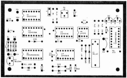
Figure 3. Parts placement on the circuit board for the 4 + 1 Decoder.
References
- Touch-Tone is a Bell trademark. For background on DTMF encoding and decoding see: Nassar, Dale: "DTMF Encoding and Decoding," Radio-Electronics, December 1986, p. 65.
- Paquette: "A Time Delayed Tone Decoder," QST, February 1977, p 16.
- Model HD-1530 Touch-Tone Decoder, Heathkit Electronics, Benton Harbor M1. Auto-Kall AK-10, Matron Electronics, 695 W. 21st Ave., Eugene OR 97405.
- Time-DTMF Emergency Decoder Kit (//LJM2RK, also called STORM-ALERT), Metheny Corporation, 204 Sunrise Drive, Madison IN 47250.
- PC boards are available from Midland Technologies, 34374 East Frontage Road, Bozeman MT 59715, tel 406-586-1i90.
- Kraman: "Single Tone Decoders," Ham Radio, Aug 1978, p 70.
- Nowland, Harold C. W8ZXH and Briggs, Stan W8MPD: "Tone-Alert Decoder," Ham Radio, Nov 1978, p64.
- Wetzel: "Tone-Alert Monitor," Ham Radio, Aug 1980, p 24.
- Jaeger, Frank WA9SQN: "The ARES Standard Tone Alert System," QST, Jan 1981 ,p 24.
- Tanner, T. C. VE3BBI: "The London Tone Alert," QST, Nov 1983, p 35.
- Kumetz, Ronald P. Jr. N2ENW: "The DTMF-64 2 Decoder," QEX, Apr 1987, p 4.
- Tanner, T. Ced VE3BBI: "The Miniaturized, Simplified London Tone Alen," QST, Feb 1987, p 30.
WA3LTJ, Andrew Mitz.