Solution: AGC
A circuit with wide applications
One of the neatest things to come along in ham gear is hands-free operation. I like to work while I operate, which means I have a nasty tendency to back too far away from the mike. My other operating habit involves 2 meters and a noisy old car. Drives me nuts having to adjust the volume as different stations with different deviations and mike habits check in.
The solution is an automatic gain control (AGC). This generic building block answers a million needs.
What is an AGC?
An AGC is an amplifier with control over its gain. The gain is varied as the input changes. If it is very rapid (fast as a cycle of the input), the device becomes a compressor. Compressors serve useful functions; they control noise and increase modulation density, which allows maximum modulation and lowest noise floor. This is important when communicating in a very noisy channel.
If the input is slower, the AGC only averages out the audio level to make it more or less the same. If an actual compressor is used, an AGC would go before it. The AGC is then used to control the audio level before major "processing" is applied.
Operational amplifiers
Op amps make it easy to design all sorts of amps and signal processing units without having to worry about the internal dynamics of the amplifier itself. This is why I have chosen to use them. In Figure 1, you can seethat I use two amplifiers. The first is the gain control element itself and the second is an output buffer. If you want to take a microphone level input, you need a microphone-toline level amplifier ahead of the AGC. If a microphone level output is required, you need a dropping pad on the output.
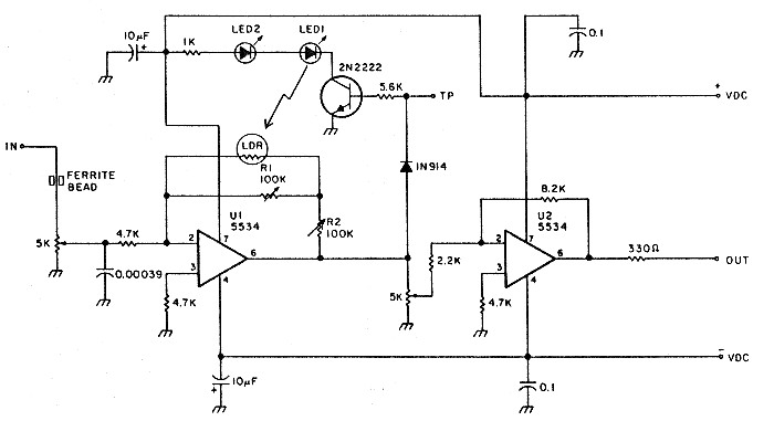
Fig 1 - Circuit for the AGC.
The gain control amplifier is a simple op amp with a variable resistance in the feedback loop. This resistance is keyed to the output of the amplifier. The control element is a CdS cell, available for pennies from your local Radio Shack. This is tied to an LED; as the output from the amplifier rises, the LED lights and reduces the resistance in the feedback loop, which consequently reduces the gain.
Potentiometers
There are four pots on the AGC board. The first controls the input level. It allows you to set the input in the middle of the active AGC range.
Two pots control the characteristics of the AGC. The pot in series with the CdS cell sets the minimum gain of the device. At minimum resistance, it has minimum gain under full input and maximum AGC control. The pot parallel to the CdS cell restricts the maximum gain of the stage. At minimum resistance, the AGC is at minimum gain and there is no AGC action. At maximum resistance, the AGC has the most control.
The three pots can be set to control the characteristics of the AGC amps. With the AGC working hard, any input from +20 dB to -30 dB comes out at about 0 dB. See Figure 4. In most communications circuits, this will also bring noise up to average levels. This ability is a bit much, so the controls allow you to reduce the range of the AGC. The fourth pot controls the output level. This convenience makes matching the next stage easier.
Versatile applications
The small PC board fits easily in most units. Any sane construction method, however, will work. The two 5534 op amps are put in one 16-pin socket. The CdS cell is super-glued to a standard red LED with the top portion filed flat, almost to the LED junction. Optical coupling is pretty tight. The CdS cell/ LED needs to be light-tight. I dip it in black paint then wrap it in black electrical tape. If light gets into the CdS cell, it will reduce the amplifier gain the same as if a strong audio signal had been applied.
It's best if the power supply is ± 15 volts, but even at ± 5 volts, the device performs rather well. When the series LED (identical to the one on the CdS cell) is visible, significant gain reduction is occurring.
A setup using the regular audio is most often ideal.
One of the results of the low parts count and easy to obtain parts is a certain amount of distortion. At about 1% it would just begin to be heard in a good stereo system, but not even close to noticeable in a communications circuit.
The uses for the circuit are endless-phone lines, phone patches, recorders, and so forth.
Parts List
| Qty | Description |
|---|---|
| 2 | 100k potentiometer, R1 & R2 |
| 2 | 5k potentiometer |
| 2 | red Light Emitting Diode, LED1 & LEO 2 |
| 1 | 1N914 diode |
| 1 | 2N2222 transistor |
| 2 | 10 µF electrolytic capacitor |
| 2 | 0.1 µF capacitor |
| 1 | 390 pF capacitor |
| 1 | 8.2k 1/4W resistor |
| 1 | 5.6k 1/4W resistor |
| 3 | 4.7k 1/4W resistor |
| 1 | 2.2k 1/4W resistor |
| 1 | 1.0k 1/4W resistor |
| 1 | 330 ohm 1/4W resistor |
| 1 | Ferrite Bead |
| 2 | NE5534 opamp IC, U1 & U2 |
| 1 | CdS photo resistor, LOB |
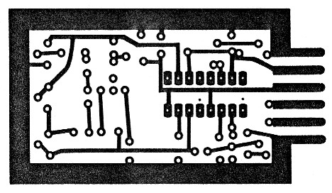
Fig 2 - Foil diagram.
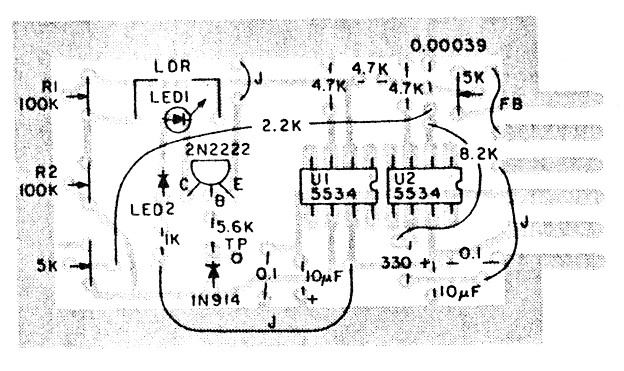
Fig 3 - Parts placement diagram.
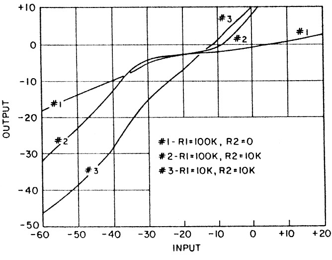
Fig 4 - Three pots control the characteristics of the AGC amps.
KA9NEH, Fred Baumgartner.