The delta-yagi ... a solution
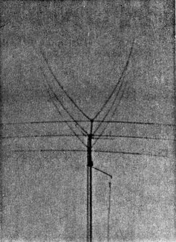
The captivating Delta-Yagi!
In these days of sharply increasing prices this form of duo-band antenna yields good performance for the monetary outlay involved. The band combinations only to be limited by the strength of character of the builder. The basic design is non-critical in terms of variance of the basic design and available building materials. Several different forms have been built by the co-authors, utilising different construction techniques and basic antenna design. After 12 months of comparison between two similar forms of this antenna, antenna perform. ance appears equal. They therefore conclude that this antenna provides a dual band capability with good performance without a considerable monetary outlay on an interlaced or trapped antenna system.
Introduction
In 1983, VK2JMG (ex-VK2KMG, VK2NIB and VK3NIB), moved from Melbourne to Wagga Wagga and traded a small inner city flat for a large suburban block. At last he had somewhere to contemplate an antenna farm. In researching back-copies of AR, an article by ` VK2VPN entitled Delta-Vagi was found (November 1980). This article described how a Delta Yagi had solved his problems.
In VK2JMG's case, he had acquired a four` element 10-metre Yagi and had a desire for 15-metres, a fascination with quads and limited finance. The Delta-Vagi seemed perfect and a two-element Delta Quad was constructed to . share the same boom as the 10-metre Yagi.
Performance of both antennas was good, in comparison with other local stations using more power (better than the FT-7 used by VK2JMG), and trapped beams, a DX station's report would be comparable and occasionally greater. The size of the 15-metre Delta Quad was enormous on the ground, but relatively "small" in the air. The latter illusion led to neighbour acceptance quite quickly. The wind survival factor initially was of great concern. A technique of parking the array into the prevailing wind allowed the antenna array and light' weight rotator to easily survive winds that tore trees apart! This form of antenna had certainly captivated VK2JMG.
Barry VK2MUZ, gained his call in mid-1986, and had been previously been involved in helping to erect and adjust the Delta Yagi arrangement at the VK2JMG QTH.
This antenna was also to prove a fascination and upon gaining his call he decided to build a 15-metre Yagi, and 10-metre quad version, each of three elements.
After exhaustive research on pricing components, it was decided the best overall value for money was to purchase a commercially manufactured beam for 15-metres and construct the quad himself. Subsequently, a 15-metre beam was selected which has proven performance. Importantly, it also has a boom large enough to support the three-element quad without added extra support.
The Delta-Vagi was constructed and the entire cost remained far below that of a trapped or interlaced commercial array. This antenna has been in the air for over 12 months and its performance has been more than satisfactory on both bands.
Also, in early 1986, VK2JMG purchased a home elsewhere in Wagga and the recent success of Barry's antenna prompted the building of a similar unit. This new antenna was significantly lighter in gauge due to materials available. The construction techniques varied to accommodate this aspect. As the two antennas were similar in design, comparison in friendly competition was undertaken. The two systems are the same height above sea level and, after 12 months, the results gained are similar. This leads to the conclusion that the Delta Yagi system is fairly non-critical in terms of basic constructional techniques and provides reasonable performance for monetary outlay.
The rest of this article will describe the basic' antenna design, and constructional variations as used in the two forms of the antenna built. It will outline aspects which are found by experience which will hopefully stimulate constructional activity with this form of antenna array.
Construction
General
A three-element 10-metre delta quad over a three-element 15-metre Yagl. The three-over-three arrangement appears to be the best all round compromise in terms of performance, size, cost and mechanical balance for this type of antenna. On 10-metres, the three-element quad provides a similar gain to that of a four-element Yagi. On 15-metres, the three-element Yagi provides Satisfactory performance without being excessively large. Both antennas theoretically have more than satisfactory front-to-back rejection ratios which show in the finished product.
Figure 1 shows the general form of the antenna with theoretical dimensions and a table of dimensions as used in the two basic forms constructed. These should serve to assist the would-be constructor.
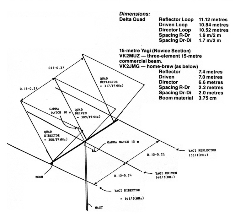
Figure 1. All theoretical values derived from The ARRL Antenna Handbook 1977.
The following notes will generally aid the constructor. These will be followed by specific details of the quad spreaders and variations, as well as the effects observed in the two delta quads built.
The delta quads are all "plumber's delight" constructions! A separate coaxial cable was used in both models to feed each antenna. The use of a single cable and remote switching system sounds attractive but has not been tried as yet! The match to each antenna is via a gamma match. The sliding-tube-type is recommended and dimensions are available in the ARRL Antenna Handbook. The two matching sections need to be opposed. Experience showed that a radiation pattern slew resulted on both bands if this was not done. The 10-metre match and 15-metre match are best mounted on each side of the boom centre as shown in Figure 1.
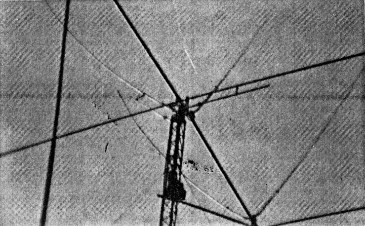
Delta Yagi - note the opposed Gamma Matches.
If a sufficiently heavy boom is used for the Yagi, the added quad elements do not necess^vrily need further support. However, if an overstay is required, ensure a good quality long-life Ultra-Violet resistant marine rope is used. A wire broken into what was thought to be non-resonant lengths, caused havoc with fine tuning of the quad. Replacement with a non-conductive rope cured the problem. The vertical support for the boom should also be a, non-conductor. PVC electrical conduit is ideal. (See Figure 2).
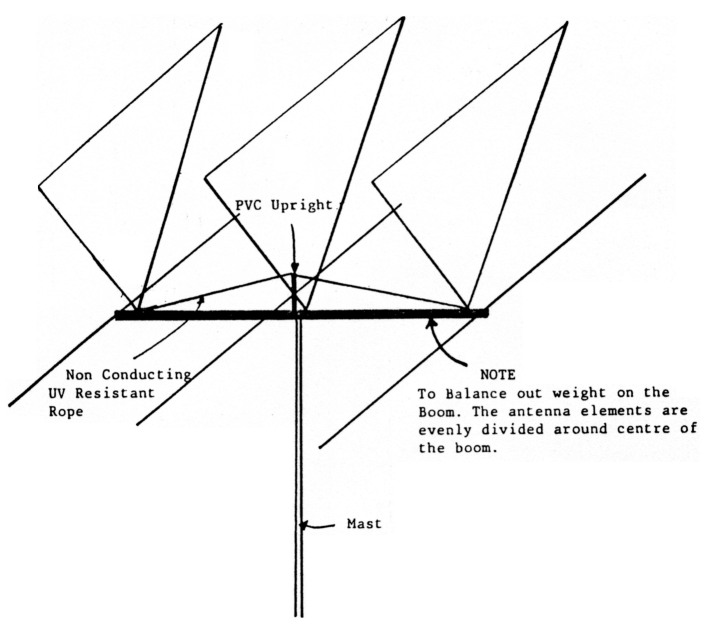
Figure 2. Note, to balance out weight on the boom, the antenna elements are evenly divided around the centre of the boom.
Another important point concerning this antenna is that it has height, width and breadth. It can therefore become difficult to manipulate or move about. By experience, once the delta loops begin to rotate, a massive torque is felt by anyone trying to hold the boom. (See Figure 3).
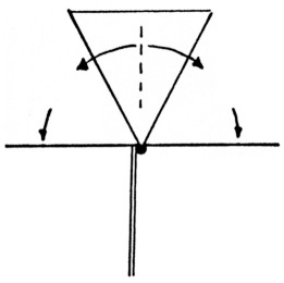
Figure 3a: Mounted on the Mast. Stable rotational effects are even.
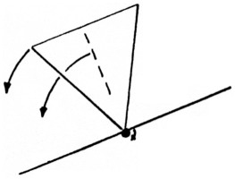
Figure 3b: During assembly or movement to the mounting point can be potentially difficult. It requires two people to safely manipulate.
It requires two people to move the array about on the ground, although once the structure is mounted firmly on the mast, and the loops balanced, it is quite stable and capable of withstanding high wind loadings.
Tuning the Antenna
The 15-metre Yagi is assembled without the delta quad. Connect it to the length of coaxial cable to be used for 15-metres, point the director to the sky and adjust the match for minimum VSWR. (It was found that this adjustment remained fairly constant even after the delta quad was added and the structure raised to final height). The delta quad elements are then added, careful design will allow the constructor to mechanically balance the array around the mast mounting point. It is suggested that carpenters' horses or similar be used with G-clamps to hold the Yagi secure during mounting of the quad elements. Alignment of the delta loops can then be made - it is easier at this height!
Tuning the quad at this stage is nearly pointless as the array is far too close to the ground. If the array can be raised to about four-metres, or so, above ground and the length of coaxial cable, to be used, attached, the VSWR adjustment will place the antenna in the "ballpark"! A touch-up will still be required when the quad is in the final position.
The method of mounting the boom to the mast must be substantial, a double clamp system to both mast and boom with a large aluminium plate is recommended. This is to negate any rotational forces exerted by the delta loops when side-on to a stiff-wind. Although wind survival of this antenna is surprising, it is recommended that, if a light weight rotator is used, (a light duty television rotator was used by the authors) the array should be parked with the director or reflector into the wind. This appears to even out any rotational forces.
Specific
It is assumed that amateurs who contemplate this design will have a 15-metre Yagi and a desire for 10-metre operation. If this is not the case, there are many good texts on the construction of Yagi antennas. If possible, ensure that the boom material is reasonably sturdy and the gauge in the walls of the tubing not too light or the quad loops will twist it over its length! (The authors tried and the wind beat them). Alternately, a commercial beam may be purchased and the delta quad added later.
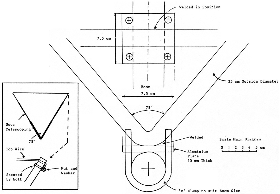
Figure 4
The most important part of the delta loop is the spreader at its apex. Figures 4 and 5 show the two forms used. Figure 4 shows the spreader used by VK2MUZ, which is very robust as he has a very windy location. Note that the apex angle is approximately 75 degrees and two U-clamps are used. The aluminium has been bent by a pipe bender as it is hard-drawn tubing which is used as tie-down railing on a semi-trailer. The 75 degree angle was used by W6SAI and W2LX in their book All About Cubical Quad Antennas, and is consistent with the VK2VPN article.
The welded U extends 60 centimetres up each arm where aluminium of a lesser diameter slides in so as to extend it to the required length. The wire over the top is a length of hard drawn copper wire, about 14 gauge, which is connected as shown in the insert to Figure 4. The VK2MUZ loops are very sturdy and operate over a significant frequency range due to their relatively large loop tubing size.
Figure 5 shows the spreader used by VK2JMG. It is much lighter than the previous one and is similar to the original version described by VK2VPN in his article. However, corner reinforcements have been added and the apex angle is 90 degrees. The increased angle has been used to ensure the sides will tension adequately. They are composed of three lengths of telescoping. aluminium tubing with the top diameter of only 1.0 centimetre. As a consequence, the loop has near vertical sides at the top. It is assumed, due to this, the antenna has an interesting response to local vertically polarised signals. This may also help with polarisation rotations during DX work as signals remain fairly constant during a "fading band". The VK2JMG loops are much lighter than VK2MUZ's, both mechanically and physically. This was necessary due to the 15-metre beam's lightweight boom.
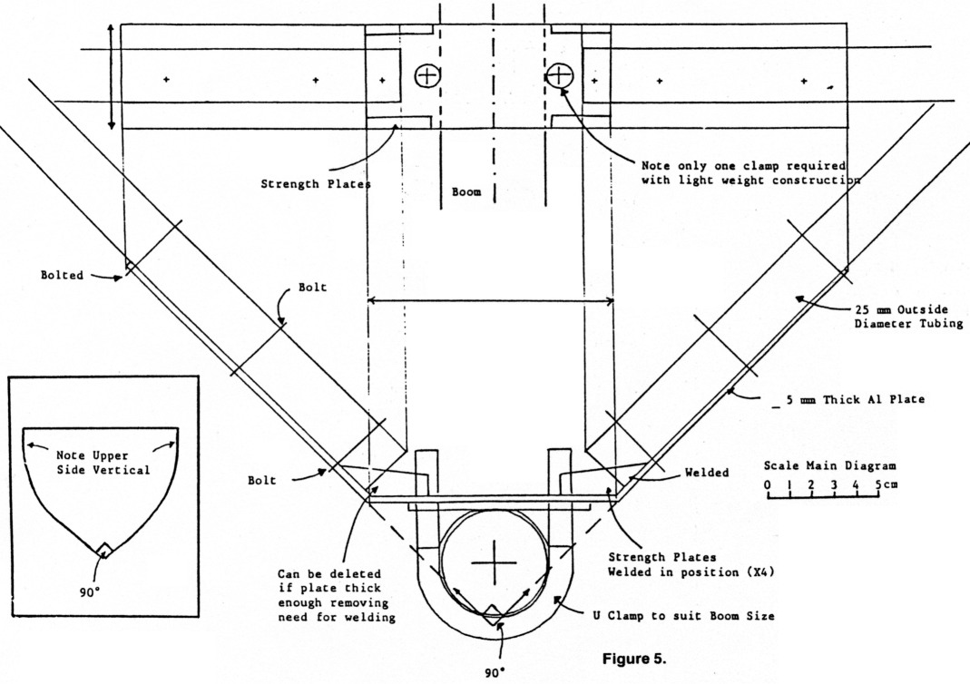
Figure 5
In terms of frequency response, this quad shows a sharper response than VK2MUZ's, however this was expected!
Both delta quads, despite minor differences, show essentially equivalent gain with reasonable front-to-back ratios on the SSB portion of the 10-metre band. The interaction between bands is minimal. If listening on 10-metres and transmitting on 15, the "bleed-over" is no worse than two Yagis sharing the same mast.
Conclusion
Both authors admit to a fascination with this type of antenna design. The information presented has been distilled from a desire to understand and make a decent idea work! Further development work will continue to optimise the system as they research, experiment and learn more about the delta antennas. In the meantime, it is hoped this article will stimulate others to construct a Delta Yagi.
References
- HOWISON, D A, VK2VPN. Delta Yagi - the answer. Amateur Radio, November 1980.
- OWEN, Arthur, WOWFB. Delta Loop Construction - five-elements on 10. Amateur Radio Action, Vol 2 No 12.
- ORR, William I, W6SAI & COWAN, Stuart D, W2LX. Radio Publications, Second Edition, Seventh Printing 1980. Wilton Conn.
- The ARRL Antenna Book, American Radio Relay League, 13th Edition, Fourth Printing 1977. Newington Conn.
- The Radio Amateurs Handbook, American Radio relay League, 59th Edition 1982. Newington Conn.
VK2JMG, M Glisson and VK2MUZ, Barry Gilmour.