A VLF-LF receiver - 10 kHz to 500 kHz with resistance tuning
Introduction
Few communications receivers tune to frequencies below 500 kHz and because of this, many radio enthusiasts are unfamiliar with this section of the radio frequency spectrum which supports numerous radio services.
Likewise, the writer had no receiver which could tune these frequencies and set out to design a simple receiver for just that purpose. The superheterodyne receiver described is the result. It has been designated a VLF-LF receiver, because it tunes the VLF-LF range from 10 to 300 kHz, but it also tunes part of the MF spectrum from 300 to 500 kHz. The VLF and LF bands have their own unique useful characteristics and these will be discussed further on.
The receiver design is a little different from the usual form. It has no variable capacitors or inductors except for one preset trimmer in a trap circuit. Tuning is carried out by a potentiometer, the resistance of which sets the frequency of the heterodyne oscillator. The RF end is untuned and the receiver bandwidth is set by two inexpensive ceramic filters in the IF channel. All inductive elements are provided by stock lines of miniature RF chokes.
Because of the low frequencies involved, it has been possible to use a number of excellent integrated circuit packages which would be unsuitable on the HF bands. The circuit diagram of the receiver is shown in figure 1 and the following discussion refers to elements in that diagram.
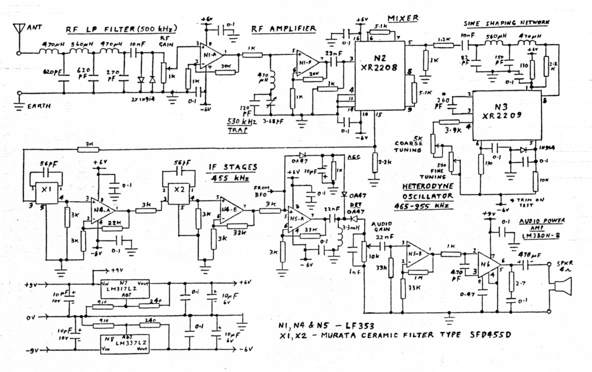
Figure 1 VK5BR VLF-LF receiver circuit diagram (Refer also to fig 4 for BFO)
The mixer stage
The mixing is carried out by an operational multiplier package type XR2208. This device is suitable for use at frequendes up to 8 MHz, and as a mixer at low frequencies its performance is outstandng. Performance tests at an input "frequency of 200 kHz and an intermediate frequency (IF) of 455 kHz have produced the following results:
- Conversion gain (Ratio of output level at 455 kHz to input level at 200 kHz): minus 6 dB.
- Equivalent noise level at input: 10 microvolts in a 1 kHz band.
- Third order intermodulation products: At input levels below 70 microvolts, products are below the noise floor. Even at 1 volt input, the third order products are 55 dB below signal level at 455 kHz.
- Level of signal at the output, equal in frequency to the input signal: 33 dB below the level at the input.
- Level of signal at the output, equal in frequency to the local oscillator frequency: 53 dB below the level of the oscillator at the mixer input.
- The low level of third order intermodulation products adds up to a low order of nuisance intermodulation beats or "birdies". The low level of local oscillator signal in the output assists in achieving operation with the oscillator frequency close to the intermediate frequency, as is needed when tuning at signal frequencies down to 10 kHz.
The Tunable Local Oscillator
For a tunable oscillator, precision oscillator package type XR2209 was selected so that variable resistance tuning could be applied. This device can be operated at frequencies up to 1 MHz and for an R-C tuned oscillator, has the excellent temperature stability of 20 parts per million per degree Celsius. For the maximum oscillator frequency of 955 kHz required, frequency drift over a 20 degrees change is therefore only 360 Hz.
The XR2209 can be connected for either square wave or triangular wave output, the latter of which is fed to the mixer via a sine shaping filter. The filter is used to reduce the possibility of oscillator harmonics mixing with high level high frequency signals, which manage to get through the RF filter at the receiver input and produce unwanted IF beats.
The tuning is carried out by two poten tiometers, one for coarse tuning and one for fine tuning. The fixed tuning capacitance and the limiting resistance in series with the two potentiometers, are trimmed to obtain an oscillator frequency range of 465 to 955 kHz, which is 455 kHz higher than the tuning range of 10 to 500 kHz. The coarse tuning potentiometer is connected to a dial which is calibrated in coarse frequency. The values of resistance and capacitance have been selected to suit the full resistance range of the coarse potentiometer. If a vernier dial is used with a shaft rotation of only 180 degrees, the value of limiting resistance can be decreased and the value of fixed capacitance increased to correct for this.
RF & IF Amplifcation
To provide RF and IF gain, JFET operational amplifier packages type LF353 have been used. These are an 8 pin DIL package containing two amplifiers with a 4 MHz gain-bandwidth product. At the frequencies involved, a gain of 100 for each package. The RF amplifiers are actually set to realise a gain at low frequenciesof 20 per unit, giving a total gain of 400. Of course, this gain decreases at the high frequency end of the tuning range.
One LF353 package is used for RF amplification and one and a half LF353 for IF amplification. The remaining odd half is used as an audio driver following detection.
The RF Circuit
The front end of the receiver is broad-banded up to a frequency of around 500 kHz above which higher frequencies are attenuated by a low pass filter. The function of the low pass filter is to reject signals at image frequency which, as it happens, fall within the broadcast band. It also rejects higher frequency signals which could mix with harmonics of the local oscillator to produce a 455 kHz IF beat. The 3 dB cut off point of the filter is set at 500 kHz and its response is 55 dB down at the 2nd harmonic of the cut off frequency.
In the coupling circuit between the two RF amplifier stages, a trap circuit is also included. In the first instance, the receiver was made to reject signals above 420 kHz and the trap was fitted to reject direct signal pick up at the intermediate frequency. Direct pick up at 455 kHz proved to be no problem and this was attributed to the properties of the XR2208 which balance out the input signals. Furthermore, the receiver could also be tuned across 455 kHz with no undesirable effects. In consequence of this, the input filter was changed for a cutoff frequency of 500 kHz to extent the range of the receiver. The only problem with this change was that it opened up the RF end to signal entry at the extreme end of the broadcast band. Strong local station 5UV on 530 kHz mixed with the second harmonic of the heterodyne oscillator to produce a signal when the receiver was tuned to receive 37.5 kHz. Furthermore, if the RF gain was set too high, 5UV would cross modulate other signals. To eliminate this problem, the trap was set to the 5UV frequency just above 500 kHz.The IF Circuit
The selectivity of the receiver is achieved with two Murata type SFD455D ceramic filters in the IF channel. These are a low price unit essentially made to replace 455 kHz IF transformers in transistor receivers. Using the two of these filters, the 3 dB bandwidth is 3.7 kHz and adjacent channel rejection is 47 dB at 10 kHz from centre frequency and 65 dB at 20 kHz from centre frequency. The response of the IF channel is shown in figures 2a & 2b. Figure 2b is an expanded version of 2a. The steep slope of the IF response enables signal reception down to 10 kHz. For this tuned condition, the heterodyne oscillator runs at 465 kHz and this must be rejected by the IF channel.
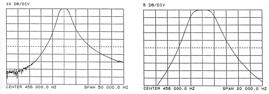
Figure 2 Intermediate Frequency (IF) Response
The values of components connected around the filters are as suggested in the manufacturers brochure but if a wider bandwidth is desired, it can be achieved by a change in these values. The writer experimented with one of these filters and found that its bandwidth could be expanded to around 7 kHz by operating with the circuit constants shown in figure 3.
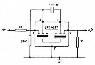
Figure 3 Ceramic Filter - Connection for wider bandwidth
Audio Stages
The IF signal is detected by a diode and following R-C filter. The audio output is fed via the half LF353 pre-amplifier to an 8 pin version of the LM380 power amplifier. The LM380 has internal thermal limiting and using heat sinking only via the circuit board pins, it can deliver an audio power of up to 1 watt into a 4 ohm load with a power supply of 9 volts.
Beat Frequency Oscillator (BFO)
Most of the signals heard within the frequency range transmit in the AM or MCW mode and the receiver was initially wired up for only that type of reception. However, there are also CW signals on the bands, such as those transmitted by the marine coastal radio, for which a BFO is needed. A BFO is also useful for detecting the presence of some of the navigational signals such as Omega. A BFO was eventually added and this is shown in an additional diagram, figure 4.
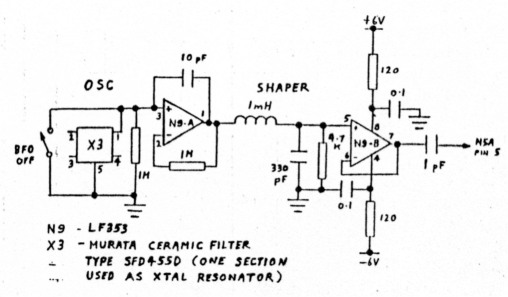
Figure 4 Beat Frequency oscillator (BFO) Circuit Diagram
The 455 kHz ceramic filters, used in the IF stages, are quite inexpensive and this provided an attraction to use a third filter for crystal control of a stable BFO. Tests on the filter showed that a crystal element could be accessed between pin 5 and any of the other pins on the filter and each element gave a parallel resonance around 456.85 kHz. Pins 1 and 2 elements were found to produce a higher Q than pins 3 or 4 elements.
Another half LF353 was pressed into service to form the oscillator in conjunction with the ceramic element across pins 1 & 5 and other components as shown in figure 4. Frequency of oscillation was measured to be 456.36 kHz, which was a satisfactory offset to 455 kHz to operate the incoming signal within the 3.7 kHz IF passband and give a suitable audio frequency beat. The series inductor and shunt capacitor at the amplifier output form a sine shaping filter fitted as a precaution in case harmonics of the BFO caused any problems. The second buffer amplifier is really unnecessary, but it was given a job to do, as it was available as a spare in the LF353 package and required no extra components.
The component values shown to make the circuit oscillate were determined experimentally on a single LF353 and a single ceramic filter. This is pointed out because, in duplicating the circuit, constants in these devices (particularly the filter) might well vary in different samples, possibly resulting in the need for a change of component values in the feedback path.
Power Rails
Split power rails of plus and minus 6 volts are used for all stages except the audio power amplifier. The split rails enable precise centring of amplifier operating points making it easy to directly couple, without capacitors, many of the amplifier stages. The 6 volt rails are derived by voltage regulators type LM317LZ and LM337LZ from a nominal source of plus and minus 9 volts. These regulators are packaged in standard TO-92 transistor cases and are very compact. The regulators are needed to stabilise the voltage, in particular to the XR2208 oscillator, as its high frequency stability can only be achieved if its power rail voltages are held constant.
Decoupling of the 6V rails is used in feeding both oscillator circuits. These are running at a high signal level and the decoupling is necessary to prevent coupling into other circuits via the power rails.
The audio power amplifier is powered directly from the positive 9 volt source and does not load the regulator.
The regulated load current is approximately 30 mA per 6 volt rail and is well within the 100 mA capacity of the regulators. The additional load current from the LM380 increases the current on the 9 volt positive supply to 37 mA in the quiescent state and to 134 mA when the power amplifier is driven to its maximum output with continuous sine wave wave signal. Under signal conditions, average current is in the order of 50 mA.
The 9 volt power sources can be two small 216 type torch batteries or twin unregulated DC supplies rectified from a transformed AC supply. If batteries are used, the positive supply must be shunted with a 2200 µF electrolytic capacitor to prevent the swinging load current of the LM380 from developing a corresponding voltage drop across the battery internal resistance. If the voltage is allowed to swing below 7.7 volts, the regulators cannot do their job and instability occurs. This also puts a limit on how far the batteries can be discharged before the regulated voltage fails. The possibility of instability is eliminated if a separate (third) battery is used for the LM380 so that supply to the regulators is unaffected by the LM380 varying load.
Overall sensitivity
For satisfactory performance, receiver generated noise level, referred to the receiver input, must be lower than the noise incoming from the antenna. At low audio frequencies, the atmospheric noise is very high and hence receiver sensitivity does not have to be as good as that normally sought for receivers operating the HF or VHF bands. In this receiver, the minimum discernible signal level is around 3 microvolts for frequencies below 100 kHz. Above 100 kHz, sensitivity falls because of the shaped response caused by the RF filter and the 530 kHz trap and to a lesser extent by the failing sponse of the RF amplifiers at high frequencies. Figure 5 plots minimum discernible signal level as a function of frequency together with a plot of atmosferic noise against frequency. The noise is that anticipated from a 10 to 30 metre antenna in a bandwidth equal to that of the receiver, or 3.7 kHz. The figures have been derived from information published in the ITT Reference Data for Radio Engineers and based on a noise level for Australia of around 45 dB above KTB at l MHz. Based on figure 5 and using the range of antenna lengths specified, the receiver has adequate sensitivity for frequencies up to 350 kHz. The receiver still operates up to 500 kHz, but owing to the shaped RF response, it has a considerble reduction in sensitivity as 500 kHz is tapproached.
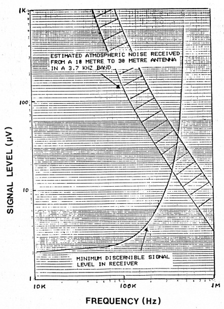
Figure 5 Minimum discernible signal level & estimated atmospheric noise level
Full automatic gain control (AGC) has not been provided in the RF and IF ciruits, partly because the LF353 amplifirs did not quite lend themselves to control of gain and partly because ionospheric handling was not anticipated on this band. Had AGC been contemplated, gain controlled amplifiers such as the Motorola MC1590 or the Plessey SL6120 might have been a better choice for RF amplifiation. Because RF gain is manually controlled, some care must be taken in setting the RF gain control to prevent receiver overload when tuning to a very strong signal, such as the local airport bacon. The placing of the gain control at RF the amplifier input might appear open to question as attenuation at its input effectively degrades the receiver noise figure. On the other hand, it is the best place to control the input signal level to pevent cross modulation in the amplier. Furthermore, at the frequencies concerned, incoming noise is generally predominant over receiver noise and the noise figure is not so important.
The main nuisance of no AGC was find to be the audio overload which occurred when shifting the tuning from a weak signal to a very strong signal. This effect was reduced by applying a form of AGC which lowered the gain of the last IF stage on very strong signals. To achieve this, DC voltage is rectified from the IF output of the stage and is applied to a germanium diode connected at the stage input. The variable resistance of. the diode acts as the shunt element of an inverted L network. The higher the signal voltage, the higher is the diode current, the lower is the resistance of the shunt element and hence the greater is the loss in the network.
One might well ask why this AGC system was not applied at the RF input as is usually done. This, in fact, was experimented with but found to encourage cross modulation from strong stations within the passband of the RF filter. This is a problem with broadband RF stages. There is no selective tuning to attenuate the level of the strong signal and the variable slope gain characteristic, needed for AGC control, is also a good mixing medium for the strong signal to cross modulate any other signal.
Alignment
The only tuned circuit is the trap. This can be aligned by feeding a modulated signal at a fairly high level into the receiver input at a frequency just above 500 kHz and adjusting the series trimmer for minimum audio output. One might choose to select the frequency of the lowest frequency local broadcast station, as did the writer. In the writer's case, the receiver was tuned to 37.5 kHz and the trap set for minimum signal from 5UV (refer to the previous discussion in the section on the RF circuit).
The only other possible adjustment is the setting of the heterodyne oscillator frequency to cover the frequency range of 465 to 955 kHz, over the tuning range of the coarse potentiometer control. This is done with the fine potentiometer control set to centre position. Trimming of the capacitance across pins 2 & 3 of N3 and the fixed resistor at pin of N3 could be necessary to suit individual samples of the XR2209 package. Its frequency range can be checked using a frequency counter connected across its output or by feeding the receiver input with a signal generator set to the extremities of the input frequency range, 10 kHz and 500 kHz.
Notes on Assembly & Components
There is nothing particularly critical about the receiver layout except that the circuit wiring should flow from input to output in order, as is normal practice and outputs should be kept away from inputs. It is not an arduous task to hardwire the whole unit (except for controls) on a small piece of Vero board. The writer's experimental receiver was fitted on a card space of 12 cm x 10 cm.
All the inductors used are the miniature ferrite cored types such as the Siemens range of RF chokes type 878 108-S. These are about the size of a small resistor, are colour coded like a resistor and can easily be mistaken for one. There are a few precautions to observe in mounting these chokes. Unlike toroidal cored inductors, the field around them is not confined and they should be mounted with extended leads, at least 1 cm off any metal on the circuit board, to prevent change of inductance and lowering of Q. If two of them are mounted close together, they should be mounted at right angles to reduce interaction between their fields.
As a general rule, capacitors with a low resistive component should be selected for filters and tuned circuits and this also applies to the filters and trap circuit in this receiver. Most people choose ceramic capacitors for use in their projects because of their small size, but their resistive component varies from sample to sample in a batch and it is often quite high. Unless they can be carefully selected for low resistive component, using an impedance bridge or Q meter, they should be avoided if possible. Mica capacitors are good but are usually much larger. There are some high quality ceramic capacitors made, such as the Vitra-mon VP31 range, but they might be diffi cult to obtain at the local electronics store.
The only other components, which require particular mention, are the capacitor and variable resistances used to control the frequency of the heterodyne oscillator. The capacitor across pins 2 & 3 of N3 should be a good stable type (perhaps a mica) and the potentiometers should be non-inductive with good resolution. Good quality one-watt carbon or cermet types of potentiometer are suggested to give nice smooth tuning. This is emphasised because there are some very poor potentiometers on the market today, particularly in the miniature variety. On of their faults is the high degree of mechanical backlash which seems to be caused by the elasticity of the bush sealing the shaft. Fortunately this backlash is steadied when the shaft is loaded down by the reduction gear on a tuning dial.
What Can Be Heard
The VLF and LF bands have their own unique useful characteristics. Transmission is by ground wave, virtually unaffected by reflection from the ionosphere and because of this, transmission is highly predictable and very useful for direction finding and other forms of radio navigation. Atmospheric attenuation falls as frequency is lowered and given sufficient radiated power, signals at VLF travel large distances around the earth's surface. A difficulty is the massive aerial system needed to achieve some order of antenna efficiency and hence radiated power.
Another limitation is the restricted amount of channel space, not suitable for wideband systems. For example, one television channel of around 6 MHz bandwidth, on its own, takes up 20 times more band space than the whole of the VLF and LF spectrums put together.
Radio waves are highly attenuated when passing through water but waves in the VLF region are attenuated the least. (This was discussed in an article by the writer in Amateur Radio, April 1987.) Because of the comparatively low attenuation, the VLF band is used for communication to submarines.
Within the Australian region, there are many strong signals transmitted in the VLF and LF band and the part of the MF band tuned by the receiver. Included in these are the following:
Omega navigation system can be heard in a frequency band of 10 to 13 kHz. There are actually five different frequencies transmitted which are switched in a certain order of eight segments in a ten second time frame. One of the Omega stations is located in Victoria, Australia.
The North West Cape VLF station can be heard with a frequency shift of 100 Hertz between 23.25 and 23.35 kHz.
A proliferation of aeronautical homing beacons (known as non-directional beacons or NDBs) within the spectrum of 200 to 420 kHz, transmit continuous carrier with morse ident code and some also with voice aerodrome traffic or information.
Australian maritime coastal radio stations operate with CW on a range of fixed frequencies between 420 and 490 kHz and listen for merchant ships on 425, 468, 480 and 512 kHz. The maritime distress frequency is 500 kHz.
Throughout the world, there are several stations in the VLF-LF spectrum which transmit standard time and frequency. GBR (Rugby UK) is well known for its time services on 16 kHz. MSF (Rugby) also transmits on 60 kHz. At low frequencies, these typical signals are ducted around the earth in a type of wave guide formed by the D layer and the earth. With a bit of luck, one might pick up some of these.
There are various teletype services which can be heard from time to time. Of course it is difficult to identify who they are unless you can decode their signals.
In Europe, frequencies between 150 and 300 kHz are used for long wave broadcasting but at these frequencies, distances are too great for reception within Australia.
For those enthusiasts who are interested in short wave listening and identifying various stations, there is another field of endeavour in long wave listening.
Other Options
We have discussed the design of a complete VLF-LF receiver but there are a few other simple options which might be attractive to others interested in these bands. If you have an existing receiver with a 455 kHz IF channel, you could build just the RF end of the receiver described and feed the XR2008 mixer output into the second receiver IF stage, via a switch which selects either the VLF-LF front end, or the existing receiver RF end.
Another option is to use the VLF-LF RF end as a converter and feed the mixer output into the second receiver tuned at the low frequency end of the broadcast band. A frequency would have to selected clear of strong broadcast carriers and the connecting lead would have to be carefully shielded. The capacitor across pins 2 & 3 of the XR2209 oscillator would also have to be decreased to shift the oscillator frequencies up a little. Do not try to shift it up too far as the frequency limit of the XR2209 is specified as 1 MHz, although you might get it to operate a little higher than that.
In the receiver described, the IF channel was specifically designed with a narrow bandwidth and a steep out of band slope so that 10 kHz could be tuned. If an attached receiver option is used, tuning quite as low at 10 kHz might be restricted if the receiver bandwith happens to be too wide.
Considering some other options, a different type of RF amplifier could easily be used, perhaps with better performance at the MF end of the tuning range. It is strongly recommended that you stay with the XR2208 as a mixer, because of its balanced mixing type of performance and its low order of intermodulation products.
Summary
A receiver has been presented which tunes the VLF and LF bands and part of the MF band. The receiver makes use of a number of integrated circuit packages and circuit techniques, perhaps a little unusual in radio receivers. Use of the XR2209 oscillator' package with resistance tuning and a broadband RF front end eliminates the need for a ganged tuning capacitor. The XR2208 operational multiplier performs as a mixer at the frequencies concerned with outstanding performance. The dual operational amplifier package LF353 has been put to work as an RF and IF amplifier. A section of an inexpensive ceramic filter is used as crystal control for a stable BFO. There are no coils to wind as all the inductors are inexpensive RF chokes of preferred value, available off the electronics store shelf.
The receiver has more than adequate sensitivity on the VLF and LF bands. Its sensitivity falls on the MF band as 500 kHz is approached.
Included in the discussion is an introduction to what can be heard on the VLF, LF and lower MF bands. Apart form the complete receiver in itself, a few alternative options have been presented on how a VLF-LF front end could be added to an existing receiver. For the keen experimenting listener, the VLF-LF bands might well be another new field of endeavour to explore.
VK5BR, Lloyd Butler.