High S.W.R. protection for transceivers and amplifiers
This system may be used to protect any transceiver and any external amplifier from damage due to high s.w.r. operation. You can reduce replacement costs and increase your rig's operating life.
A long with the fun of operating a modern transceiver, one often experiences the following troubles with the power amplifier stage.
- When operation is attempted with a high s.w.r., damage often occurs to the loading padder capacitors. This can happen even when the transmitter is operated for only a second; for example, if a few dits are accidentally keyed into the wrong antenna. The problem is especially serious when the transmitter is equipped with broadband circuits.
- When tetrode tubes are used, there is a special problem. Under high s.w.r. conditions, or during tune-up while loading adjustments are being made, the screen current often rises far beyond the maximum allowable limit. This causes tube failure, internal arcing, and driver and power supply damage.
- Even under normal operation into a proper load, there is often a spike in the r.f. output, occuring at the beginning of a transmission, which causes arcing in the PA circuit components. This arcing can cause burnt contacts in the bandswitch, requiring extensive repairs.
- When used as a driver for a linear amplifier, the amplifier relay is often slower than the transceiver circuits. This means that while the amplifier is switching, the transceiver operates into an open circuit, causing all the above problems associated with high s.w.r. This problem is especially likely to occur when the transceiver incorporates break-in.
System Performance
With this system, the transceiver may be used with any antenna, or even no antenna (signal reports may be low!), with no damage to the radio, in either the broadband or the manual mode. It allows on-the-air operation with high s.w.r., at automatically reduced input. Tuning is greatly simplified; instead of the usual method of gradually increasing the drive while constantly monitoring the screen current and adjusting the loading, the drive may be turned up and the PA controls quickly adjusted for maximum output, while the new circuit automatically keeps the screen current under control.
This system, while developed for the Signal/One CX7, will function as well in any modern transceiver. The circuits shown need no changes; the installation and connection to the existing transceiver circuitry will of course be adapted to the particular model.
The system is presently in use in more than a dozen transceivers, with uniformly excellent results.
Theory of Operation
The system consists of the following three components:
- A d.c. amplifier added to the a.l.c. circuits.
- An r.f. level detector added to the power amplifier manual and broadband tuning capacitors.
- An r.f. level detector added to the power amplifier manual and broadband loading capacitor.
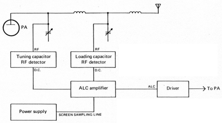
Fig 1 - Simplified block diagram of the system.
The d.c. amplifier increases the sensitivity of the a.l.c. circuits, and allows the driver to control the r.f. levels in the PA, and also to control the screen current. This eliminates the arcing and component damage. The control signals for the tuning and loading capacitor r.f. levels are provided by the added PA detectors. A block diagram of the entire system is shown in fig. 1.
The CX7 design includes a "screen a.l.c. circuit" which, however, never functions, due to the currents and voltages involved. The d.c. amplifier added in this protection system corrects this situation by adding the necessary gain. The control signal for the screen current is provided by the power supply circuit in the original design.
For transceivers other than the CX7, a screen current control circuit must be added to the power supply. This is merely a shunt in the negative screen lead; it requires a separate screen supply. Alternatively, this portion of the protective system may be omitted; the r.f. level limiting will do much to protect the screen also. If the screen protection is included, the shunt is selected so that about 3 volts appear across the shunt at the maximum allowable screen current. This value is not critical, since the fine adjustment for maximum screen current is made by the screen trimmer on the a.l.c. amplifier. The shunt should have a 3 watt rating, as its failure would damage the a.l.c. amplifier.
If an external final amplifier is utilized, it may very easily be protected in a similar manner. Screen sensing and r.f. level detecting are added to the amplifier, together with adjustment trimmers and isolating diodes as in the transceiver a.l.c. amplifier. The combined control signal is connected to a fourth input on the a.l.c. amplifier.
The A.L.C. Amplifier
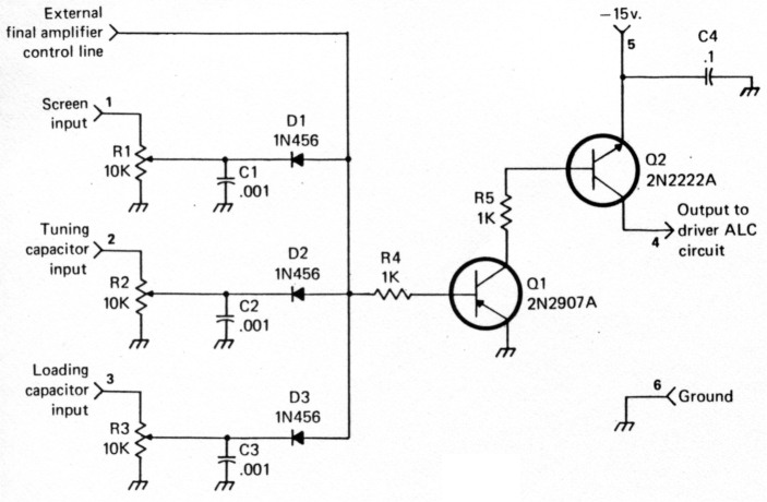
Fig. 2 - The a.l.c. amplifier.
The amplifier circuit is shown in fig. 2. It is a straight-forward d.c. amplifier, providing a.l.c. voltage for the original driver a.l.c. circuits. The three diodes isolate the three separate inputs. The three 'miniature trimmer controls separately set the a.l.c. threshholds for each of the three operating parameters controlled. The PA grid a.l.c. functions as originally designed, with no modification. R1 is adjusted so that at the maximum allowable screen current, the voltage on the screen sampling line from the power supply is reduced to the voltage level needed to turn on transistor 01. Trimmers R2 and R3 function similarly.
The amplifier is constructed on a small circuit board. It is installed wherever space is available. If the power supply does not include a low voltage negative supply, the bias supply may be utilized using a voltage divider. The voltage and regulation are not critical. (In the CX7, the amplifier board is epoxy cemented to the driver board. Diode A5-CR2, which is in the screen a.l.c. line, is removed, and the amplifer is connected into the circuit in its place, using the circuit board pads to which the diode had been connected. Operating voltage for the amplifer is obtained from the driver board.)
R.F. Level Detectors
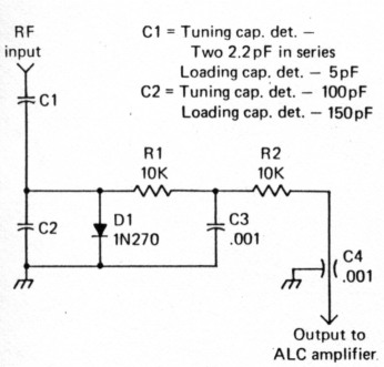
Fig. 3 - Circuit of the r.f. detector used for both tuning and loading capacitors.
The circuits for the r.f. level detectors are shown in fig. 3. They are identical except for the r.f. voltage dividers. The dividers were chosen to provide approximately 3 volts at the amplifier trimmers, which requires about 10 volts at the detector diodes. Thus dividers providing 100 times and 30 times attenuation were chosen, corresponding to 1000 volts and 300 volts peak r.f. at the tuning and loading capacitors, respectively. These levels are merely nominal; the exact threshholds are set by the trimmers, and depend on the capabilities of the transceiver's PA components.
Construction Details
Amplifier
The amplifier is constructed on a 2" by 1.3" piece of Keystone type 4230 glass epoxy board, P pattern, 0.1" grid. The trimmers are IRC type X-201-R103B. Transistors are mounted in sockets, Augat type 8059-2G1. The circuit board layout is shown in fig. 5. (In the CX7, the circuit board is epoxy cemented to the driver along a line extending from R19 to pin 262. Terminals 2 and 3 are fitted with Amp connectors as used throughout the CX7. The other four terminals are fitted with leads connecting to the driver board.)
Tuning Capacitor R.F. Detector
Parts C3, D1, R1, and C4 are mounted on a miniature terminal strip and installed inside the PA cage. Capacitors C1 and C2 are connected between the terminal strip and the tuning capacitor; they are 1000 volt NPO discs, Sprague type 10TCC-V22. C3 is a silver mica. C5 is a feed-thru mounted on the PA cage. Resistor R2 is attached directly to C5 with a short lead, for good filtering. (In the CX7, the detector is installed on the left side of the upper PA cage, above the insulator for tie point E29, and C1l is connected to this tie point.)
Loading Capacitor R.F. Detector
Parts C2, D1, R1 and C3 are mounted on another miniature terminal strip inside the PA cage. Capacitor Cl is a 1000 volt NPO disc, Sprague type 10TCC-V50, connected between the terminal strip and the PA loading capacitor. Capacitor C2 is a silver mica. Feed-thru C4 is mounted near the terminal strip, and resistor R2 is connected directly between the terminal strip and the feed-thru. (In the CX7, the detector is mounted on the front of the upper PA cage, near the broadband switch. Cl is connected to the wiper on the loading capacitor (front) section of the broadband switch, the lug with wire 493 leading to tie point E32.)
Power Supply Modification
When the a.l.c. amplifier is installed in the CX7, diode A5-CR7 should be checked. If there has been any trouble in the screen supply, this diode will probably be open and must be replaced. To prevent similar damage to the a.l.c. amplfier, change R6 on the power supply board to 3 watts, and add a 100 ohm, 1/2 watt, resistor between the screen supply rectifiers and pin 152. Also, a 1l8 a. fuse in the screen lead to the PA is recommended.
Adjustment
- Screen current. In the receive mode, use a bench power supply to apply approximately - 3 V d.c. at the screen input on the a.l.c. amplifier. Adjust the bench power supply voltage to a level corresponding to the maximum allowable screen current. Measure the a.l.c. voltage produced by the a.l.c. amplifier and adjust R1 to obtain full limiting in the controlled stages of the transceiver; this setting will vary with different models. An a.l.c. meter, if provided, will facilitate the adjustment. (In the CX7, switch the meter to a.l.c. and adjust R1 to obtain a reading of 1.0.)
- R.f. levels. Turn R2 and R3 to minimum. Realign the broadband circuits. On each band, running full power in broadband into a 50 ohm dummy load, measure the d.c. voltage obtained at the two r.f. level amplifier inputs. Select the band which produces the highest tuning capacitor r.f. level. On this band, while running full power, advance R2 until the output just begins to drop, then back off R2 so that there is no reduction in output. Select the band which produces the highest loading capacitor r.f. level, and repeat the procedure for R3.
Operation
The drive should be set at a level so that normal a.l.c. meter indications are obtained when the radio is keyed, or under normal voice conditions. The a.l.c. meter will indicate whenever a grid current, scren current, tuning capacitor r.f. level, or loading capacitor r.f. level threshhold has been reached, whichever of the four is reached first. For manual tune-up, advance the drive somewhat beyond the point where a.l.c. indication is normally obtained, and adjust the PA controls for maximum output.
K6BE/5, Mark Mandelkern