How to build a simple SWR bridge
Now that the official antenna season has started, here's a simple project that will make tuning your antenna easier.
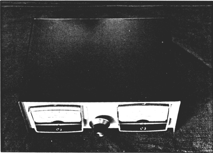
Looking down at the completed SWR bridge. It looks sleek and professional.
Here's a simple weekend project that you can build inexpensively with readily available parts from Radio Shack. The only parts you might have to hunt around for are the two 0-50 µA meters. Radio Shack does list 0-15 VDC meters, and these may be converted to read full scale with appropriate shunt resistors. Check most radio handbooks for details of selecting shunt resistors. You can also use meters reading 100 to 200 µA for this purpose.
L1, L2, and L3 are made from #12 copper wire, 4½ inches long, spaced 1/4 inch apart. They are mounted on the perf board as shown in the photographs. The perf board is mounted in a separate aluminum box within the main cabinet. R3 and R4 are a dual stereo control (sensitivity).
The shielded cable is made from ordinary hook-up wire and the shield braid of a short piece of coax. Some care should be taken with wiring of the two diodes D1 and D2. First measure the forward resistance. The reading obtained is academic, but both diodes should read the same. Next check the backward resistance, this should read almost zero. Now wire in the diodes using a pair of long-nosed pliers. Recheck the forward and backward resistance. The pliers act as a heatsink and should be held in place for a few seconds. The black bands of D1 and D2 will go to C1 and M1, and C2 and M2, respectively.
The two metal standoffs (RS 276-195) are used to secure the shield box to the main chassis, as support for the pert board, and to provide a handy terminal for C1, R2 and R1, C2 to ground. D1 and D2 are wired to the other lugs of a terminal strip (RS 274-688).
To balance the bridge simply hook up a dummy load to J2 and then apply up to 200 watts of power to J1. In the key-down mode, adjust the sensitivity control R3, R4, for a full-scale reading at M1. A smaller reading will be seen at M2 (reflected power). Now adjust R2, the balance control, for a null at M2. While adjusting R2, keep your fingers away from the pickup loops or you might experience a nasty RF burn.
That's really all there is. The photographs show how the unit goes together. The parts list indicates the Radio Shack parts numbers. However, you can fill in from your own junk box.
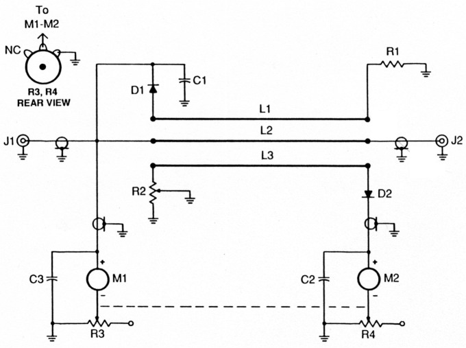
Fig. 1- Schematic diagram of the simple SWR bridge.
Parts List
| D1, D2 | 1N914 |
| C1 ,C2, C3, C4 | 1 nF |
| R1 | 68 Ω |
| R2 | 500 Ω |
| R3, R4 | 100kΩ |
| M1, M2 | 0-50 µA |
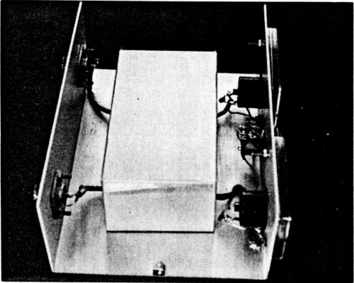
A side view showing the simple construction techniques. The small chassis box (RS 270-238) encloses the pert board strip lines as seen in the other photograph.
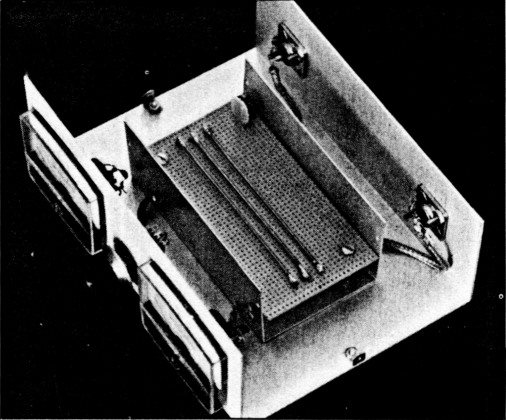
Interior viewshows the pert board, strip lines, and R2. Shielded cables enter near the bottom through small drilled holes.
VE3AEH, John J. Gray.