A new twist for the HF J-pole antenna
Feel like tinkering? AD1B describes a nifty little antenna project that also makes use of your computer.
I recently became interested in the possibility of building a compact high frequency antenna for portable workand did some reading on the subject. It seems that the price for most physically small antennas is a narrow band width and exotic coil construction. My thoughts then went towards the possibility of a J-pole antenna, a simple design that is anything but compact when used in the normal fashion, as I was to discover after I did some computations.
There has been a lot of interest in the J-pole antenna for VHF work, particularly on the six and two meter bands, but much less information on HF applications. The "J" is, however, a popular and simple vertical antenna that has been described in a large number of articles that emphasize that the J-pole features ease of construction, low cost of materials and the convenience of direct feed by coax. Another nice feature is that there is no need for a ground system or for a group of radials.
The ARRL Antenna Book describes the J-pole as a half-wave vertical radiator fed by a quarter-wave stub matching section (see fig. 1). It also indicates that the J-pole has been popular in mobile applications, although it is not as widely used as the quarter-wave whip.
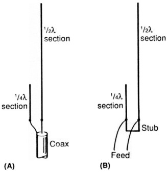
Fig. 1 - The basic J-pole antenna. At (A) it is fed with coax and at (B) twinlead or openwire.
My interests are in development of a simple 20-meter antenna for fixed and perhaps mobile work, one that does not rely on coils, traps or other electrical methods of size reduction. I wanted the derivative of a full sized antenna using some type of compacting approach for the problem of achieving a reasonable size.
How about a Helical J-pole antenna, I thought; it may have been tried, but I have never found a reference to that particular configuration. To test the concept, I used the cardboard tube from a paper towel roll and would a two meter J-pole antenna around it. The VHF antenna worked fine and seemed to offer a reasonable match to my Yaesu Memorizor. The next step was to try the concept on a larger scale. Since cardboard was impractical for the larger size of the high frequency antenna, I settled on 1.5 inch PVC tubing for a supporting mechanism.
The next question was the determination of the dimensions of the antenna; many slightly different formulas have been reported in the literature. The most useful formulas were in an article by VE2CU ((QST March, 1981), which are shown in fig. 2.
½λ section = ½λ × .965
¼λ section = ¼λ × .830
Stub = .0136λ
λ = 300/MHz Meters
Fig. 2 - The VE2CU formulas for the HF J-pole antenna. Refer to fig. 1(B).
I prepared a short BASIC program for my IBM PC in order to determine the dimensions of the J-pole at various frequencies (see fig. 3 for the program listing - it is easily adaptable to a variety of computers). Settling on 14.3 MHz, I ran the program and built the antenna from 300 ohm twin lead that I purchased at Radio Shack. The process of winding the coil around the mast is tedious, but not particularly difficult. At ten inch spacings, I made a band of electrical tape to prevent the spirals from slipping. The initial spacing between turns was about one-half inch, later trials were made with one inch spacings.
10 CLS
20 REM "J-pole program"
30 A$ = "********************************************************************"
40 FOR N = 1 TO 6: PRINT A$: NEXT N
50 PRINT
60 PRINT
70 PRINT "HF J-POLE ANTENNAS"
80 PRINT
90 PRINT "COMPUTATION OF DIMENSIONS"
100 PRINT
110 PRINT "AD1B
120 PRINT
130 FOR N	1 TO 6: PRINT AS: NEXT N
140 PRINT: PRINT
150 PRINT "	ENTER 'C' TO CONTUE"
160 Z$ = INKEY$:IF ZS = "" THEN 160
170 CLS:FOR N = 1 TO 6: PRINT :NEXT N
180 PRINT
190 PRINT "To determine the size of a J-POLE antenna for a selected HF band, enter the FREQUENCY in MHZ:"
210 INPUT F
220 L = (984/F)
230 X= .0136*L
240 Y= .2075*L
250 Z= .483*L
260 CLS
270 FOR N = 1 TO 4:PRINT: NEXT N
280 PRINT
290 PRINT "HIGH FREQUENCY 3-POLE:"
300 PRINT "  I I"
310 PRINT "  I I"
320 PRINT "  I <- .5 wavelength"
330 PRINT "  I I"
340 PRINT "  I I"
350 PRINT "  I
360 PRINT "  I   break <- separation between Y and Z"
370 PRINT "  I I"
380 PRINT "  + + coax  <- center to left; braid to right"
390 PRINT "  I I       <- .25 wavelength "
400 PRINT "  ---       <- stub (distance from short to coax)"
410 PRINT
430 PRINT "Half-wavelength:	";INT(Z*10)/10
440 PRINT "Quarter-wavelength: ";INT(Y*10)/10
450 PRINT "Antenna Length:	";INT((Z+Y)*10)/10
460 PRINT "Stub Length:	";INT(X*10)/10
480 PRINT
490 PRINT "FOR ANOTHER COMPUTATION, HIT ANY KEY...."
500 Z$ = INKEY$: IF Z$ = "" THEN 500
510 IF Z$ = "C" THEN GOTO 170
520 STOP
Fig. 3- The J-pole computer program.
Well, how did it work? Not bad, I answered myself. I live near Boston, Mass. and was able to work stations in Illinois, Arizona and Tennessee with reasonable signal quality with the antenna attached to a fence at a height of six feet above the ground.
What are the pros and cons of the compact J-pole? It is small, one version was only four feet high. It is cheap enough, with a little scrounging it should be possible to build one for under $10. It does work, my experiences were quite a pleasant surprise.
As to the cons... the helical J-pole is a compromise antenna that will never perform as well as a full-size model, but perhaps this is something that will work for you in portable or mobile applications. I suspect that the helical J-pole would be easy to clamp to the rear bumper of a car, using two clamps and a metal plate. This would certainly be a very simple and readily available antenna for anyone on a limited budget who is interested in mobile operations.
HIGH FREQUENCY J-POLE:
  I I"
  I I"
  I         <- .5 wavelength"
  I I"
  I I"
  I
  I   break <- separation between Y and Z"
  I I"
  + + coax  <- center to left; braid to right"
  I I       <- .25 wavelength "
  ---       <- stub (distance from short to coax)"

Half-wavelength: 33.2
Quarter--wavelength: 14.2
Antenna Length:	47.5
Stub Length: .9
FUR ANOTHER COMPUTATION, HIT ANY FEY.... Break in 510
OK
Fig. 4 - A sample run of the computer program.
AD1B, Thomas M. Hart.