A lightning protection system for your shack
You can improve the chances of surviving lightning damage by following the suggestions of KO9G.
Lightning is not a subject to be taken lightly. It can and does do considerable damage to amateur radio gear, household electronic equipment, and even computer software, to say nothing about the damage to home and other structures. Given the value of electronic devices in your house, and the cost of repairs brought on by direct, let-alone nearby, hits, adequate protection systems are certainly worth the time and investment.
This article covers the principles and installation of a lightning protection system based on ones developed for commercial radio installations. Such systems have provided direct-hit protection for installations up to several hundred feet high here in the Midwest, where electrical storms and thunderstorms are common, occurring even in winter months. It is derived from a presentation put together by one of the members of our local club.(1)
First things first
Lightning is "the large spark produced by an abrupt discharge of electricity through the air generally under turbulent conditions of the atmosphere." The charge moves up a pre-ionized path from ground to cloud and the current frequency exceeds 30 thousand amperes; 500 amps flow in the ionized channel between strokes.(2)
Lightning is also a series of alternating-current (AC) pulses with large amounts of energy distributed all the way across the spectrum-from DC to the microwave region. Thus, currents are readily induced in household wiring and electrical devices by near and not-so-near strikes. The fields can also be propagated for many miles through utility and telephone wires.
Lightning-induced currents take the lowest impedance path to ground. They are RF currents, and the difference between high- and low-impedance paths is a matter of very, very few ohms reactance. Even a corroded joint or sharp bend in antenna or ground leads is a high-impedance obstacle at higher RF frequencies. The objectives and methods of the lightning protection system described here, while focusing on tower-supported antennas, are relevant to any antenna system. These objectives are:
- Provide a common, lowest-possible impedance path to ground for your antenna structure(s) and system, your home's electrical system, and your electronic equipment.
- Provide the means to safely discharge lightning-induced fields before your gear and household electronics can be cooked.
- Isolate your antenna system and amateur gear from house wiring-and vice-versa-with respect to lightning-induced currents.
A common and solid ground
The first step is to establish a solid, common ground for everything: antenna supports and cables, household wiring, amateur radio and household electronic equipment, as shown in fig. 1.
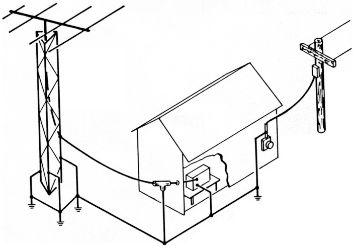
Fig. 1 - A common ground tying tower, antennas, equipment, and AC service ground is essential.
A tower's concrete base is a great insulator. The reinforcing bars and tower bolts embedded in this base are not at ground potential by any means. Also, there is significant loss-high Impedance-between tower legs (or tripod legs) as cross members and joints become corroded over time.
Tower-section joints should be bridged with ground strap or cable clamped to each leg above and below each joint; tripod legs are tied together with a continuous strap or cable clamped to each leg. Then each tower leg is grounded separately.
Next, 8 to 10 foot copper or copper-plated ground rods, at least 5/8 inch diameter, are driven into the ground 12 inches away from the tower base - one for each leg. Each rod is connected to the tower with 0 or 00 gauge wire or similarly-rated flat copper braid strap as shown in fig. 2. Heavy crimp-on connectors are used at the cable ends and connections made to legs and ground rods with bolts, or ground cable may be secured to legs and rods with stainless hose clamps or cable clamps. All connections must be mechanically secure, clean, and weatherproofed with Co-ax Seals, or similar compound.
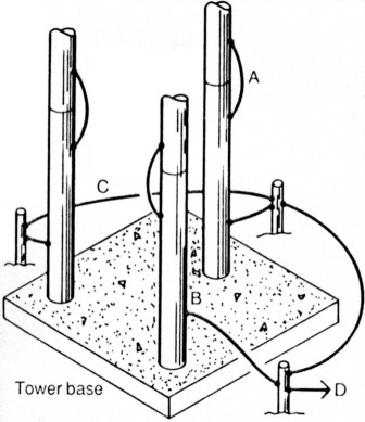
Fig. 2 - (A) Tower section joints bridged with ground strap or cable. (B) Each leg grounded to own ground rod. (C) Rods tied together with continuous conductor. (D) All tied to service entrance ground.
Coax cable braid is out. It acts like an inductor and raises path impedance. Soldered connections are also out; the solder will vaporize if your tower is struck. Use it only for corrosion protection.
Once the tower sections and legs are bonded together and grounded, tie the tower-leg ground rods together with strap or cable, using the same method used to connect legs to rods. Then tie this entire antenna support ground to a common utility or water-supply ground point.
The common tie-point is your home's AC wiring ground - at the outside service entrance. ALL ground cables from your tower or other antenna support structures, as well as any other ground rods, are ultimately brought together here. They are tied (clamped) to either the utility-installed ground rod adjacent to the meter or to the heavy exterior conduit leading from the meter. An alternative, where ground-cable runs may be long or awkward, is the water-supply pipe to your house-before the meter and outside (assuming it is not rubber or plastic from a well).
When all of this is done, you will have a continuous, low-impedance ground established from the top of your tower in common with your house ground. Both ground rods and cable are available from electrical contractors or possibly your utility company.
Now your antenna and rotator cables
Coaxial cable shields and rotator cable shields must also be grounded with the shortest, lowest-impedance path possible. The objective is to prevent currents from flowing into your shack and/or household wiring.
Antenna and rotator cable shields may be tied to tower legs with ground straps. All ground ties must be straight and downhill and made mechanically and electrically secure. The method shown in fig. 3 is recommended for antenna coax, rather than breaking cable insulation. There's a bit more work adding PL-259's, but it saves cable degradation and also gives you a convenient way to add or change cable runs. Rotator cable shield may be grounded by clamping-not just soldering-a ground strap to the shield and running it to a tower leg.
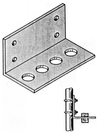
Fig. 3- One-quarter inch aluminum or steel angle plate drilled to accept coax feed-throughs as needed, and U-bolts to mount to tower leg. Mount so cable runs vertically to and from.
Once cables have left your tower (with everything running in a downhill direction), you also want to add a bit more protection before they enter your house and shack. Make a one-turn loop in each cable segment between tower and shack. This will provide additional impedance for any lightning-induced currents. The loops are also "fuses" that can blow before your gear.
Lightning arrestors or discharge devices should be installed in coax and rotator cables before they enter your house. Two types of arrestors are available for coax. One is a double-female device that provides a spark gap inside a metal tube. The other type is a gas-discharge device, such as a "Transi-Trap," marketed by Alpha Delta Communications (see ads in CQ, QST, and other magazines), which provides a voltage-dependent path to ground.
All arrestors must be securely grounded, either directly to your common ground cables or to ground rods (5-8 inch) which are then tied to your common ground system.
Rotator cables may be protected with low-voltage surge arrestors installed inside the rotator control box, one device for each conductor. They are designated GE V56ZA2. If unshielded rotator cable is used, these devices should also be installed inside the rotator housing.(3)
Why this attention to rotator cables? A local amateur, thoroughly familiar with tower installations, lowered his tilt-over tower and his antenna elements brushed against the 13K power lines at the rear of his lot. Sparks flew! It was discovered, after all the outdoor excitement, that damage was done inside as well. Currents flowing through connected rotator cable had gotten into his amateur gear and household wiring. Both the service panel and electronic equipment were damaged. Imagine what lightning could have done!
Now to the inside
With everything taken care of outside, you now want to make certain that wire-carried or induced currents can do as little damage inside as well. That means isolating and grounding everything.
A separate AC line should be used from your service panel to shack, if at all possible. At least use a circuit that has nothing else on it-especially motors, If your computer is on line. This can help take care of RFI/TVI as well as helping lightning/surge protection.
A common ground bus-#8 copper wire, flat braided strap or even ½ inch copper pipe-is run from your operating position to ground. That ground is cold-water plumbing (before the meter, if possible), not hot water pipes or electrical conduit. Or, a separate ground rod. Each piece of equipment is tied to this bus, Individually. Include transmatch, rotator control box, and power supplies. Avoid "uphill" runs and sharp bends in ground wires.
Tie this ground bus to your outside tower/house common ground system. This is a must!
Power cords, too
We're all aware that the solid-state devices inside your rigs, TV's, etc., don't take the electrical abuse that good, old vacuum tubes did-especially from static charges or voltage surges. Add to that software, especially in ROM's, for operating peripherals like your new TNC. You've got two ways to go. You can remember to unplug everything and break out in a cold sweat in the middle of the night with the first lightning flash trying to remember if you did. Or, you can protect your equipment rather easily, plugged in or not. As a first step, use three-wire AC power cords-even protecting "oldies but goodies" by replacing two-wire cords. And, use surge protectors and line-cord filters throughout, between your gear and the AC outlet(s). If you're a home-brewer, include MOV surge protectors as part of the project. Remember, these methods work best when you have proper equipment grounds.Wrapping it up
Your investment in amateur radio and household electronics that are exposed to and easily damaged by lightning-generated currents is considerable. It is worth the effort to plan for their protection-and the protection of your house-and do it as thoroughly as possible.
A well-grounded system, regardless of your antenna system's complexity or simplicity, has additional benefits. It's a vital part of preventing or reducing TVI/RFI. Antenna efficiency can be improved. Operating and maintenance safety is Increased. You will also be protecting equipment and software from switching and other nonlightning transients that often cause damage.
This system approach to lightning protection is not a "quick fix." You won't do it in a day, since your time is limited. Start with the tower and inside-the-shack grounds and work towards the middle as time and money permit. Once completed, you'll be secure for years to come.
Notes
- Paul Sexauer, W9JTO, 29 W. 155 Lee Rd., West Chicago, IL 60185.
- "Lightning," McGraw-Hill Encyclopedia of Science & Technology, Vol. 7, 1982, McGraw-Hill, Inc., New York, NY.
- "Protect Your Equipment from Damaging Power Line Transients," Stuart and Collick, OST, Vol. LXVI, Feb. 1982, pp. 35-38, American Radio Relay League, Newington, CT. NI
KO9G, Peter Altman.