Tired of having your tower just sit there using up valuable real estate just to support a beam? Put it to work on a few more bands and keep it real busy.
This article describes the low-band antenna system at KD9SV's location. The 160 meter success with a tower only 70 feet tall could easily be applied to a shorter tower for 80 meters.
When I returned to the amateur radio ranks after some 15 years off the air, I bought a used, freestanding, 70 foot tower. After I installed a TH6-DXX antenna at 71 feet, I found I was in pretty good shape on 10, 15, and 20 meters, but I still needed something for the three low-frequency bands.
I wanted to give the new tower a clean, uncluttered look and avoid a lot of wire antennas which would detract from the appearance of my lot. To get on the low bands I fed the tower on 160 meters, used a half sloper (1/4 wave) on 80 meters, and fed a 33 foot long rotary dipole loaded off center on 40 meters. This gave me all six bands with just one piece of wire in the air.
Design approach
When we were given the new WARC bands, I started looking for a means to get on 12 and 17 meters. I decided to convert my 40 meter rotary dipole into a trap dipole for 12 and 17 meters using the tower as a vertical radiator for the three low-f requency bands. My friend Lynn, WA9GFR, and I found it possible to make a very effective vertical antenna out of a 50, 60, or 70 foot tower with a beam antenna for top loading. This equipment is something many amateurs already have in their arsenal.
I took this approach mainly because a short tower of about 50 feet with a small triband beam on top is nearly 5/8 wavelength long on 40 meters and close to wavelength on 80 meters. The low angle of radiation from this system will do a much better job of working long-haul DX on those bands than an inverted Vee or dipole mounted at this height.
The KD9SV vertical radiator
As with any vertical system, performance depends upon the thoroughness of your ground radial system and the efficiency of your antenna match. I recommend a minimum of 20 quarter-wavelength radials for the lowest frequency band, but use a number that's practical for your location.
The 70 foot tower at KD9SV is grounded through several ground rods. It also has a ground radial system of approximately 20 radials 120 feet long, with 30 additional radials about 60 feet long. Fig. 1 shows details of my antenna system.
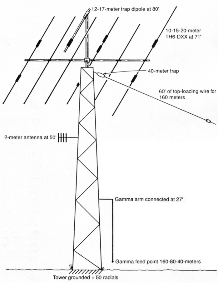
Fig. 1 - KD9SV antenna system.
As a result of past experience and new insights gained while working on this project, I came up with the following guidelines which I believe provide a logical approach to multiband matching of a single vertical tower:
- The gamma arm must be less than 1/4 wavelength long at the highest frequency (in this case, 7.3 MHz).
- Work on the lowest band first, then proceed to the next higher band. Any "tricks" you use to help the lowest frequency will force changes in the higher frequency bands.
- To prevent high-angle radiation lobes, make sure the antenna isn't electrically . longer than % wavelength at the highest frequency. (I had to put a 40 meter trap in a top-loading wire that had been added to electrically lengthen the tower on 160.)
I used a Vector impedance meter, which took the guesswork out of determining the tower's feedpoint impedance. I made the gamma arm out of 5/8 inch copper pipe. The arm is attached to the tower at a height of 27 feet and spaced 30 inches from the tower. I began matching at 160 meters by tuning out the gamma-arm inductive reactance with a series capacitor. The feedpoint impedance resistive component was only about 15 ohms. Although my TH6-DXX triband Yagi provided some top loading, I added an additional top-loading wire (see fig. 1) to make the tower electrically longer and raise the feedpoint impedance.
I tuned out the reactance of the final configuration with a 600 pF capacitor. The resulting impedance was closer to 25 ohms than to 50 ohms. This was within a 2:1 VSWR of 50 ohms, and it looked as if either additional top loading or a 2:1 transformer would give me what I wanted on 160 meters.
Because I wanted to be able to feed the tower on the three low-frequency bands from a single feedpoint, I decided to investigate matching on 80 and 40 meters before finalizing the 160 meter match. Experience told me that approximately one quarter of the capacitance, or about 150 pF, would be the starting point for matching at 80 meters. A 120 pF series capacitor presented an impedance of 25 ohms at 3.8 MHz.
As both 160 and 80 meters seemed to match easily to about 25 ohms, Lynn and I decided to keep what we had and finish the match on both bands with a 2:1 broadband transformer. We found the perfect solution in W2FMI's book Transmission Line Transformers.(1) I constructed a 2.25:1 transformer consisting of 6 turns of #14 wire trifilar wound on an FT240-61 core (see fig. 2). A shunt coil of about 100 microHenries at the feedpoint (67 turns of #20 insulated wire on a T200A-2 core) fine-tuned the input impedance on 160 meters.
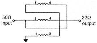
Fig. 2 - The 2.25:1 broadband transformer.
If you attempt something similar on your tower, you must match the resulting resistance when the gamma-arm reactance is tuned out. For example, if your impedance is nearer 12 ohms than 25 ohms, a 4:1 transformer would be appropriate. An unbalanced-to-unbalanced transformer is essential for this application. Do not use a balun transformer.
Adding a 40 meter match through the same gamma arm and transformer presented quite a challenge. Initial impedance measurements indicated that the O was extremely high, and that a simple match wouldn't be possible. I also suspected that the 160 meter top loading would make the tower electrically longer than % wavelength. We made a few onthe-air tests using a crude preliminary match. Signal-strength comparisons from several contacts indicated high-angle radiation.
Our final 40 meter solution involved placing a 40 meter trap in series with the top-loading wire which had been added for 160 meters (see fig. 3). The original top-loading scheme is still in place on 160 and 80 meters, but now the effective radiator on 40 meters is comprised of just the tower with the top loading of the TH6-DXX beam. The impedance I needed to match boggled my mind. WA9GFR came to the rescue once again with a clever, but simple, matching network.
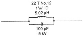
Fig. 3 - The 40 meter trap.
Matching feedpoint impedances
WA9GFR did all the impedance matching using a Smith Chart impedance-matching computer program he had written called SCHART.(2) After you enter the impedances you wish to match, the program lets you experiment with all possible types of matching elements. It also permits cascading sections. The resulting impedances are listed in tabular form and can be plotted on a Smith Chart. (You can use your computer for plotting if you have a graphics card.)
We discarded several Intermediate approaches, but the final system was easy to match on 160 and 80 meters. A simple series capacitance brought the impedance to approximately 25 ohms; the broadband transformer did the rest. After optimizing the system for the lower f requencies, we faced a real challenge with 40 meters. The Smith Chart matching program proved invaluable in finding an easy solution to a mind-boggling set of impedances.
The computer-generated results of the 40 meter matching network are shown in Table 1 and fig. 4. Highly active impedances with magnitudes of over 1000 ohms seemed to indicate that a broadband match would be impossible. Experimentation with physical networks would have been prohibitively time consuming. However, playing "what if" with the computer yielded an answer in just a few minutes.
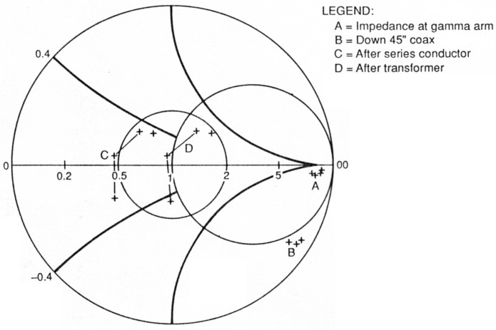
Fig. 4 - Plot of SCHART results for 40 meter match.
| Freq (MHz) | RS (ohms) | XS (ohms) |
|---|---|---|
| These were your load Impedance Inputs: | ||
| 7.000 | 1169.000 | -675.000 |
| 7.100 | 766.000 | -643.000 |
| 7.200 | 614.000 | -430.000 |
| 7.300 | 634.000 | -296.000 |
| Added 45 inches of series transmission line of 50 ohm impedance and velocity factor of 0.66. | ||
| 7.000 | 22.273 | -178.240 |
| 7.100 | 23.474 | -166.363 |
| 7.200 | 30.914 | -157.990 |
| 7.300 | 37.222 | -158.127 |
| Added series inductor of 3.79 micro Henries. | ||
| 7.000 | 22.273 | -11.108 |
| 7.100 | 23.474 | 3.158 |
| 7.200 | 30.914 | 13.918 |
| 7.300 | 37.222 | 16.168 |
| Added step-up transformer of impedance ratio 2:1. | ||
| 7.000 | 44.546 | -22.215 |
| 7.100 | 46.948 | 6.316 |
| 7.200 | 61.828 | 27.837 |
| 7.300 | 74.445 | 32.337 |
Choosing a 30 inch length of coax, we "rotated" the impedances on the Smith Chart to the point that a simple series inductor could tune out capacitive reactance for a good 50 ohm match. However, we ultimately chose a 45 inch line because I wanted to use the transformer on all three bands. Now a series inductor of about 3.7 microHenries presented an impedance of about 25 ohms, which was transformed to 50 ohms through the transformer.
Fig. 5 shows a VSWR plot across each band. We achieved a good broadband match on 160 meters and most of 40. Although the bandwidth is narrow on 80 meters, a remotely controlled motor-driven capacitor provides easy matching from the station on that band.
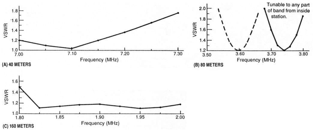
Fig. 5 - VSWR plot for the three bands.
Mechanical description
Because my tower is freestanding, I added top loading by connecting a wire near the top of the antenna. If you have a typical guyed tower, you can use your uppermost set of guys for top loading by placing insulators in the appropriate spots. Insulate your bottom or middle guy wires from the tower.
Remember that good ground connections are essential for successful vertical radiators. Details of my ground clamp are shown in fig. 6.
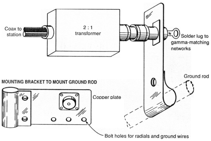
Fig. 6 - Ground-clamp mounting details.
Be sure to bring all coax cables and control cables down to ground level before running them into the station. I run a TL922 amplifier and don't have any RF in the shack.
Summary and results
A single gamma arm is used to feed a 70 foot tower on 160, 80, and 40 meters. All three matching networks described for the three bands are mounted at the base of the tower in a waterproof box and are switched with Jennings RB3 vacuum relays. Due to the narrow bandwidth on 80 meters, I use a motor-driven capacitor on that band (tuned from the station). The 80 meter matching capacitor performs double duty as part of the total capacitance on 160 meters. Individual matching networks for each band are shown in fig. 7; the combined networks with relays and transformers are shown in fig. 8.
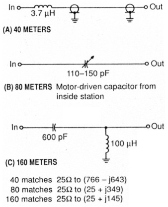
Fig. 7 - Matching networks for each band.
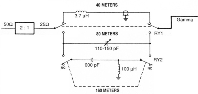
Fig. 8 - Final configuration of three-band matching network.
The VSWR is deceptively low across the 40 and 160 meter bands. After all, a dummy load has a good VSWR. One factor that influences the bandwidth of any antenna is its length-to-diameter ratio. My antenna tower is 42 inches wide at the base, which helps increase its bandwidth.
The proof of any antenna system is how efficiently it radiates. My 40 meter performance stateside is exceptional, with good DX results as well. My tower is electrically too long for optimum performance on this band. A 50 or 60 foot tower with a typical tribander on top should give better DX performance. My 80 meter performance is very good; I've made many solid contacts into Europe and Africa. This system was also used to work Bouvet Island (3Y5X) on 160, 80, 75, and 40 meters.
My goal was to have an efficient antenna on 160 meters, without my lot looking like an antenna farm. This system really radiates on 160. Although I'm not an experienced contester, I finished in the top 10 worldwide in the 1989 CQ WW 160 Meter Contest. If you're looking for an improved low-angle radiator on 160, try my approach. By using a shorter tower you should get similar results on 80 and 40 meters.
References
- Jerry Sevick, W2FMI, Transmission Line Transformers, Chapter 6, ARRL, 1987.
- This is one of several programs on the disk "WA9GFR Communications Engineering Software," which is available from the bookstore with a manual for, $19.95. (Available in either MS-DOS or Commodore-64 formats.)
KD9SV, Gary Nichols and WA9GFR, Lynn Gerig.